
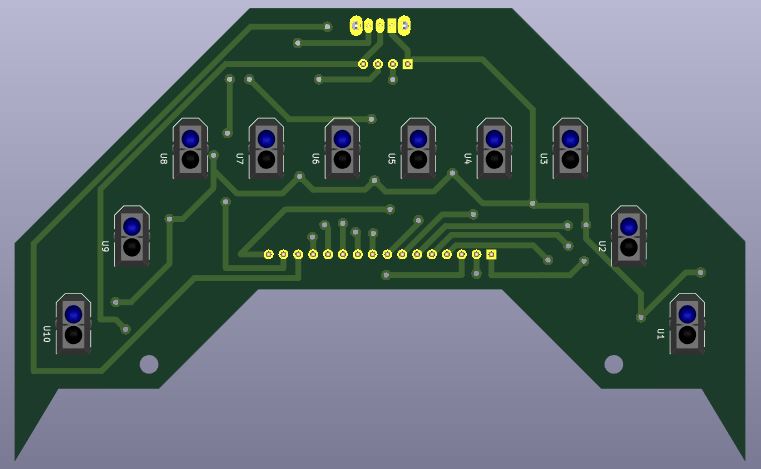
2 layers43.9 × 27.7 mm

I designed a LFR from scratch including the PCBs for main board and a custom sensor array. I designed this because I saw a friend of mine going into robotics competetions, so I also wanted to participate in them but I…
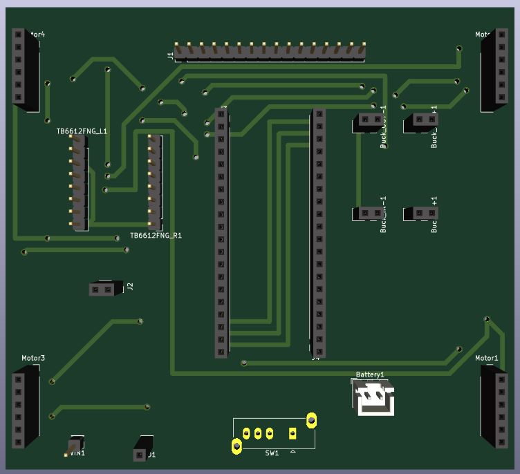
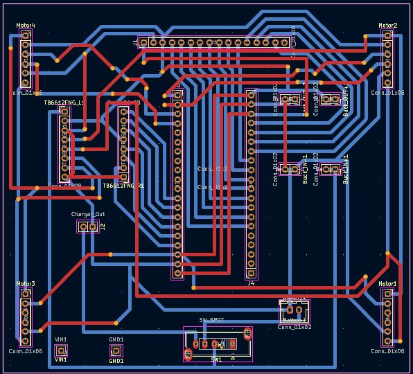
LFR is an open-source printed circuit board by bsce26023, from the bsce26023/LFR repository on GitHub. It is a 2-layer board of 110 × 100 mm with 19 parts on 53 nets, routed with 326 tracks and 38 vias.
Its parts include 5 connectors and 1 switch.
I designed a LFR from scratch including the PCBs for main board and a custom sensor array. I designed this because I saw a friend of mine going into robotics competetions, so I also wanted to participate in them but I didn't have a robot that I could take to those competetions, so I finally built one myself. I chose STM32 because in some of those events there is a requirement that your robot should not have wireless connectivity, so the first thing that came into my mind was arduino uno but it is very slow and basic compared to other microcontrollers available on market then after some research I had two options Raspberry Pi Pico RP2040 or a STM32 Black Pill. raspberry pi pico had only 3 analog pins so I went with STM32.
To View the 3D assembly --> Assembly
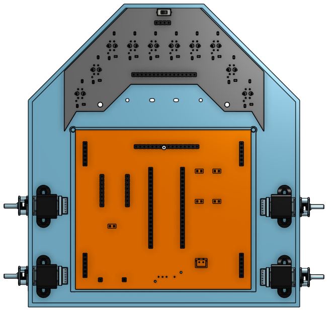 | 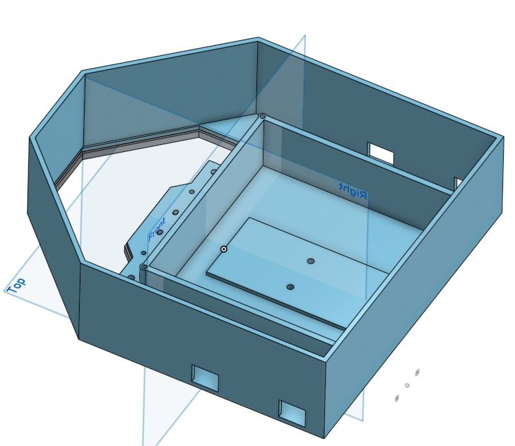 | 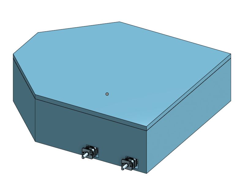 |
I've decided the components based on affordability, speed, availability and ease of use. Starting with the micro controller I've selected STM 32 BlackPill and for motors I've selected 3000rpm 6v N20 motors with encoders for fast speed to drive these motors I've chosen TB6612FNG motor driver because it has low voltage drop and also it is way lighter than L298N. I've decided to use a 2S Li-Po battery which is about 7.4v which can power the motors with ease and to power STM32 I'd use a step down buck converter to convert these 7.4v into 5v so we don't damage the STM32 to charge the battery I'd use a 2S charger and for the sensors I've designed a custom sensor array.
To talk about the connections, I'd Start with the Power connections. The battery provides 7.4v which goes to VMOT pin of motor driver and buck converter. the buck converter then outputs 5v which goes to VSYS on Pico. Now we have 3 voltages. i.e. 7.4v, 5v and 3.3v. now the 3.3v goes to VCC and STBY pin of TB6612FNG and VCC pin on Sensor Array.
Now lets talk about the Data and Logic Signals. The GPIO pins from 0 to 18 will be connected to sensor array and GPIO pins 19,20, 21, 22, 26, 27 will be connected to PWMA, AIN1, AIN2, PWMB, BIN1 and BIN2 respectively.
At the end the AO1, AO2 and BO1, BO2 will be connected to left and right motors respectively.
[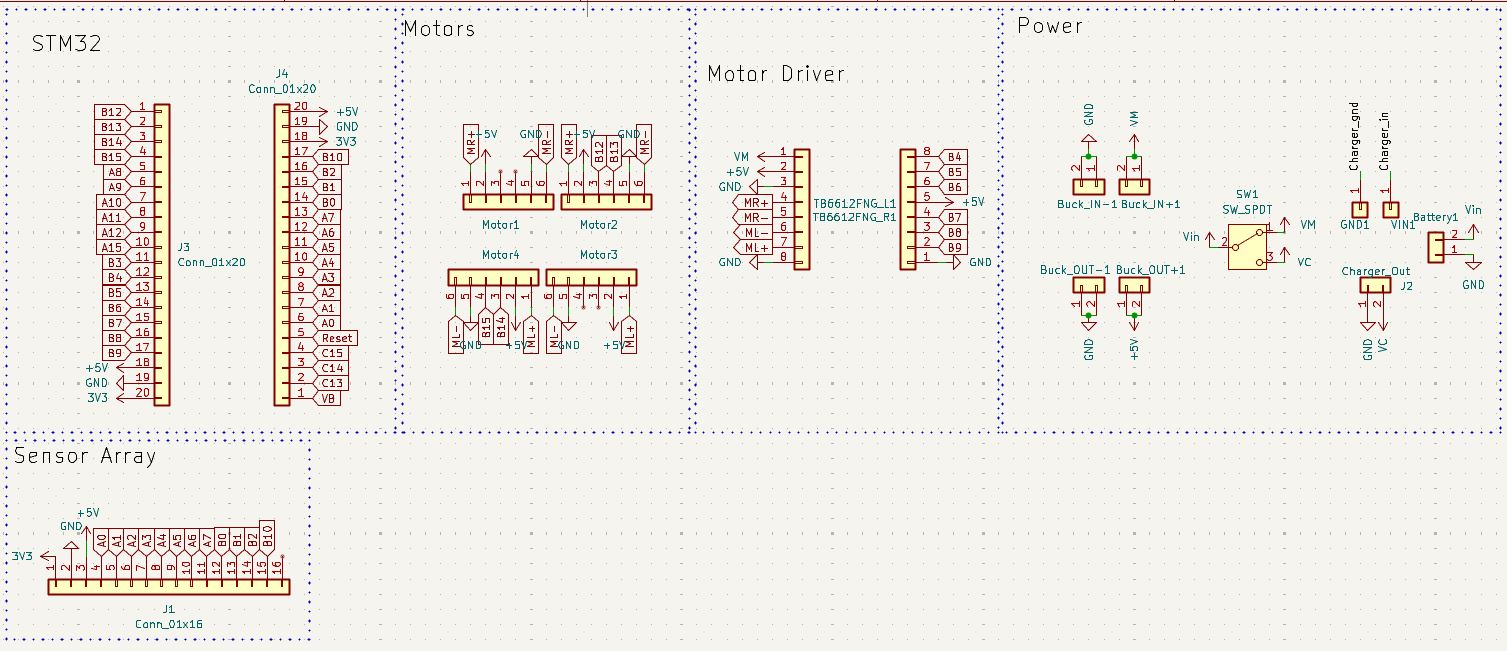 ]
| Schematics | Tracks |
|---|---|
 |  |
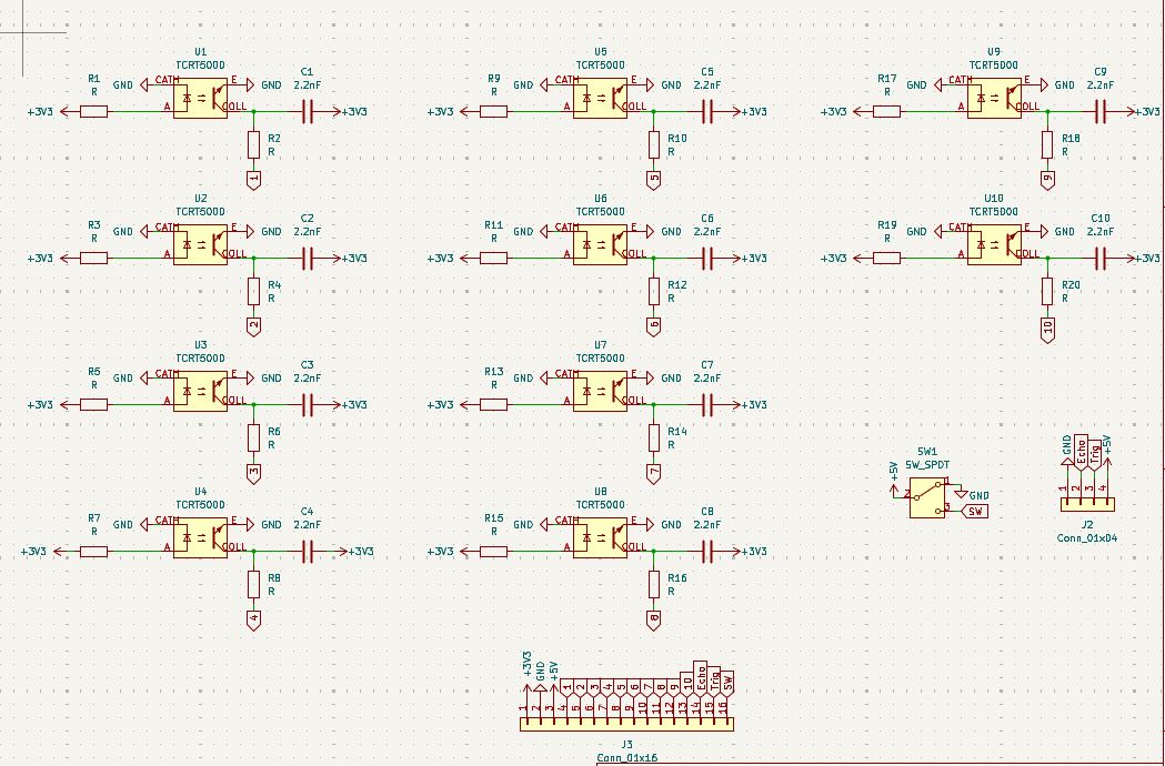
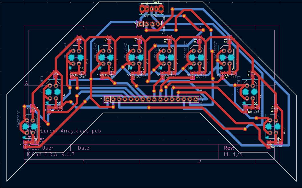
I designed the schematics for the sensor array, it is the working principle is inspired from the QTR-16RC sensor array. I designed this because traditional sensors and sensor arrays look too uncool, so I had to design something that looked aesthetic and visually pleasing.
| Schematics | Tracks |
|---|---|
 |  |
Because STM32 boards lack native USB bootloaders out-of-the-box like standard Arduino boards, flashing firmware requires a specific procedure using either an ST-LINK V2 programmer or the built-in UART system memory bootloader.
M1, M2).To flash code to an STM32 board, wire an external ST-LINK V2 programmer to the board's SWD pins:
| ST-LINK V2 Pin | STM32 Target Pin | Function |
|---|---|---|
| 3.3V | 3.3V | Power Supply |
| GND | GND | Common Ground |
| SWDIO | PA13 (DIO) | Serial Wire Data |
| SWCLK | PA14 (CLK) | Serial Wire Clock |
Note: Ensure the target board is powered either via the ST-LINK's 3.3V pin (if current draw is low) or via an independent battery/bench supply.
platformio.ini or Arduino board settings match your exact STM32 part number (e.g., stm32f103c8).| Name | Purpose | Quantity | Total Cost (USD) | Link | Distributor |
|---|---|---|---|---|---|
| PCB | PCB | 2 | 17 | https://cart.jlcpcb.com/shopcart/cart/ | JLCPCB |
| Mounting Brackets | Mounting motors | 1 | 3 | https://a.aliexpress.com/_c41oltrB | AliExpress |
| N20 Wheels | Wheels for Motors | 4 | 10 | https://a.aliexpress.com/_c3mDdjNx | Ali Express |
| Caster Wheels | Caster wheels | 2 | 4 | https://a.aliexpress.com/_c2yFCmMd | AliExpress |
| Slide Switch | Power Switch | 1 | 2 | https://a.aliexpress.com/_c3g6KmzX | AliExpress |
| TB6612FNG | Motor Driver | 1 | 4 | https://a.aliexpress.com/_c3bzgEgz | AliExpress |
| N20 Motors | Motors with Encoders | 4 | 25 | https://a.aliexpress.com/_c39Rykzn | AliExpress |
| Capacitor | Capacitance | 1 | 3 | https://a.aliexpress.com/_c3Ig4r1X | Aliexpress |
| Resistors | Resistance | 2 | 5 | https://a.aliexpress.com/_c3G1MsVL | Aliexpress |
| Limit switch | Bump sensor | 1 | 2.5 | https://a.aliexpress.com/_c3uz2Isv | Aliexpress |
| Ultrasonic sensor | Measures distance | 1 | 6 | https://a.aliexpress.com/_c35Zat1R | Aliexpress |
| TCRT5000 | Sensor | 1 | 7 | https://a.aliexpress.com/_c3RbgmiN | Aliexpress |
| Header pins | Soldering on pcb | 2 | 4 | https://a.aliexpress.com/_c4B0APx7 | Aliexpress |
| Mp1584 | Buck converter | 1 | 4.5 | https://a.aliexpress.com/_c4qnSguh | Aliexpress |
| Charging module | For charging battery | 1 | 2 | https://a.aliexpress.com/_c3Dtj3BL | Aliexpress |
| STM32 | Microcontroller | 1 | 6 | https://a.aliexpress.com/_c3GJD5FF | Aliexpress |
| Soldering Iron | For Soldering | 1 | 15 | https://epro.pk/product/soldering-iron-station-adjustable-temperature-esd-safe-kada-936-in-pakistan/ | Epro |
| Customs | - | - | 60 | - | AliExpress |
| Shipping | - | - | 20 | - | JLCPCB |
| Total | - | - | 200 | - | - |
| Qty | Value | Footprint | References |
|---|---|---|---|
| 4 | Conn_01x02 | Connector_PinSocket_2.54mm:PinSocket_1x02_P2.54mm_Vertical | Buck_IN-1, Buck_IN+1, Buck_OUT-1, Buck_OUT+1 |
| 4 | Conn_01x06 | Connector_PinSocket_2.54mm:PinSocket_1x06_P2.54mm_Vertical | Motor1, Motor2, Motor3, Motor4 |
| 2 | Conn_01x08 | Connector_PinHeader_2.54mm:PinHeader_1x08_P2.54mm_Vertical | TB6612FNG_L1, TB6612FNG_R1 |
| 2 | Conn_01x20 | Connector_PinSocket_2.54mm:PinSocket_1x20_P2.54mm_Vertical | J3, J4 |
| 1 | Battery2 | Connector_JST:JST_XH_B4B-XH-A_1x04_P2.50mm_Vertical | J5 |
| 1 | Charger_Out | Connector_PinSocket_2.54mm:PinSocket_1x02_P2.54mm_Vertical | J2 |
| 1 | Conn_01x01 | Connector_PinHeader_2.54mm:PinHeader_1x01_P2.54mm_Vertical | VIN1 |
| 1 | Conn_01x01 | Connector_PinSocket_2.54mm:PinSocket_1x01_P2.54mm_Vertical | GND1 |
| 1 | Conn_01x02 | Connector_AMASS:AMASS_XT60-M_1x02_P7.20mm_Vertical | Battery1 |
| 1 | Conn_01x16 | Connector_PinHeader_2.54mm:PinHeader_1x16_P2.54mm_Vertical | J1 |
| 1 | SW_SPDT | Button_Switch_THT:SW_Slide_SP3T_Straight_CK_OS103012MU1QP1 | SW1 |
It measures 110 × 100 mm and has 2 copper layers, 1.6 mm thick.
19 parts. The full list of its parts is on this page, with links to each part's symbol and footprint where PCBKit's library has them.
From the bsce26023/LFR repository on GitHub, at the commit this page was made from: the board is Main Board/PCB.kicad_pcb and its schematic Custom Sensor Array/Sensor Array.kicad_sch. PCBKit opens the board in the browser, with nothing to install.
Its repository states no licence, so its author keeps all rights: ask bsce26023 before reusing the design.

hackclub/OnBoard
💡 Join 1,000 teenagers and make your first PCB with a $100 grant!

polpo/picogus
Emulation of ISA sound cards and CD-ROM on Raspberry Pi Pico (GUS, SB/Adlib, MPU-401, Tandy, CMS, Panasonic CD-ROM) with USB mouse/joystick support


nkitanov/iaq_board
IAQ Board is a DIY (Do-It-Yourself) device for measuring internal air quality


Ardumower/ardumower
Develop an open source robotic lawn mower (HW+SW reference platform)

zmaker/arduino_cookbook
gli sketch del nuovo progetto Arduino Cookbook e dei video di YouTube