4 layers70 × 100 mm
Txrx-1
brucemack/sdr2
This is a homebrew SDR rig with no dependency on external computers/soundcards/etc.
98 partsGPL-3.0

 brucemack/sdr2
This is a homebrew SDR rig with no dependency on external computers/soundcards/etc.
Tx-1 is an open-source printed circuit board by brucemack, from the brucemack/sdr2 repository on GitHub, published under the GPL-3.0 licence. It is a 2-layer board of 68 × 41 mm with 55 parts on 31 nets, routed with 221 tracks and 54 vias.
It is built around the LM4562NA and SN74CBT3253D. Its parts include 25 capacitors, 18 resistors, 4 connectors and 3 ICs.


This is a homebrew SDR rig with no dependency on external computers/soundcards/etc.
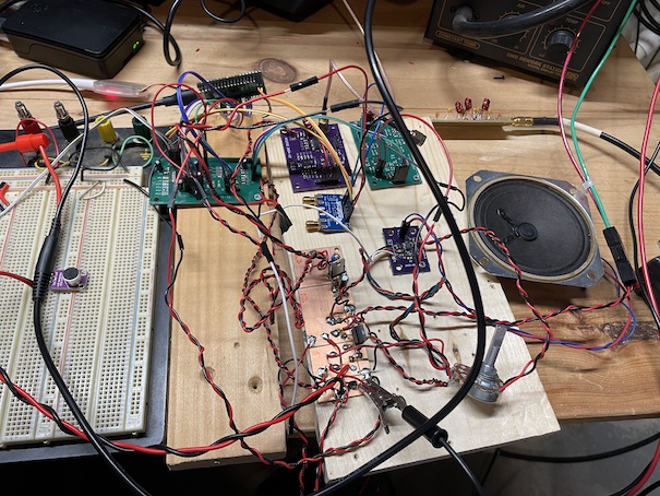
One-time setup of make process:
    git submodule update --init
    mkdir build
    cd build
    cmake -DPICO_BOARD=pico2 ..
Command used to flash code to board:
~/git/openocd/src/openocd -s ~/git/openocd/tcl -f interface/cmsis-dap.cfg -f target/rp2350.cfg -c "adapter speed 5000" -c "rp2350.dap.core1 cortex_m reset_config sysresetreq" -c "program main.elf verify reset exit"GP0 - (Reserved for UART0 TX)
GP1 - (Reserved for UART0 RX)
GP2 -
GP3 -
GP4 - I2S SCK out to PCM1804 ADC and PCM5100 DAC
GP5 - RST out to PCM1804 ADC
GP6 - I2S DIN in from PC1804 ADC
GP7 - I2S BCK out to PC1804 ADC
GP8 - I2S LRCK out to PC1804 ADC
GP9 - I2S DOUT out to PCM5100 DAC
GP10 - I2S BCK out to PCM5100 DAC
GP11 - I2S LRCK out to PCM5100 DAC
GP12 - User button input 0
GP13 - User button input 1
GP14 - PTT input
GP15 -
GP16 - I2C0 SDA for Si5351 (Addr 0x60)
GP17 - I2C0 SCL for Si5351 (Addr 0x60)
GP18 - I2C1 SDA for display and IO expander
GP19 - I2C1 SCL for display and IO expanderP0 - User indicator LED output
P1 - Audio amplifier enable (Low=enable output, high=shutdown amplifier)
P2 - ADC Input Select (Low=Microphone preamp out, High=QSD channel out)
P3 - TX band select 0
P4 - TX band select 1
P5 - RX band select 0
P6 - RX band select 1
P7 - Transmit PA enable (active low)See Horowitz and Hill (3rd ed, section 5.16, figure 5.88) for a description of the instrumentation amplifier configuration used on the receive board. Gain for this amplifier is controlled determined by 1 + 2 Rf / Rg. Notice that the feedback path is tapped after a 47 ohm resistor to set the output impedance of the stage.
Assuming Rf is 520, Rg is 100, the theoretical gain is about 11.
dBm = 30 + 20 * log(Vrms/sqrt(Z0))
Consider the PCM1863 ADC?
Consider the TS5A4624 analog switch (logic high = 2.4V w/ 5V supply)
Consider PCF8574A IO expander: https://www.ti.com/lit/ds/symlink/pcf8574a.pdf?ts=1728869550852&ref_url=https%253A%252F%252Fwww.mouser.com%252F
RF Transistor: https://www.nxp.com/docs/en/data-sheet/BFU590G.pdf
PCM1804 Datasheet PCM5100 Datasheet
The library gets built once in a parallel project:
    cd ~/pico
    mkdir CMSISDSP
    cd CMSISDSP
    git clone https://github.com/ARM-software/CMSIS-DSP.git
    git clone https://github.com/ARM-software/CMSIS_6.git
    cp $PICO_SDK_PATH/external/pico_sdk_import.cmake .
Then setup the CMakeLists.txt shown below and build:
    mkdir build
    cd build
    # IMPORTANT! pico2 build enables the generation of FPU instructions
    cmake -DPICO_BOARD=pico2 ..
    make -j4
What the CMakeLists.txt looks like:
cmake_minimum_required (VERSION 3.6)

# Pull in Pico SDK (must be before project)
include(pico_sdk_import.cmake)

set(HOME $ENV{HOME})
set(CMSISDSP ${HOME}/pico/CMSISDSP/CMSIS-DSP)
set(CMSISCORE ${HOME}/pico/CMSISDSP/CMSIS_6/CMSIS/Core)

# Define the project
project (cmsis-dsp VERSION 0.1)

# Initialise the Pico SDK
pico_sdk_init()

add_subdirectory(${CMSISDSP}/Source bin_dsp)

target_compile_options(CMSISDSP PUBLIC
    -Wsign-compare
    -Wdouble-promotion
    -Ofast -ffast-math
    -DNDEBUG
    -Wall -Wextra  -Werror
    -fshort-enums
    #-fshort-wchar
)
Example of referencing the built CMSIS-DSP library in a client project:
set(HOME $ENV{HOME})
target_include_directories(main PRIVATE
  ${HOME}/pico/CMSISDSP/CMSIS-DSP/Include
  ${HOME}/pico/CMSISDSP/CMSIS_6/CMSIS/Core/Include
)
target_link_libraries(main
  pico_stdlib
  ${HOME}/pico/CMSISDSP/build/bin_dsp/libCMSISDSP.a
)SDR2 Rig - Copyright (C) Bruce MacKinnon KC1FSZ, 2025
This program is free software: you can redistribute it and/or modify it under the terms of the GNU General Public License as published by the Free Software Foundation, either version 3 of the License, or (at your option) any later version.
This program is distributed in the hope that it will be useful, but WITHOUT ANY WARRANTY; without even the implied warranty of MERCHANTABILITY or FITNESS FOR A PARTICULAR PURPOSE. See the GNU General Public License for more details.
You should have received a copy of the GNU General Public License along with this program. If not, see https://www.gnu.org/licenses/.
FOR AMATEUR RADIO USE ONLY. NOT FOR COMMERCIAL USE WITHOUT PERMISSION.
| Qty | Value | Footprint | References |
|---|---|---|---|
| 9 | 0.1uF | Capacitor_SMD:C_0805_2012Metric_Pad1.18x1.45mm_HandSolder | C3, C5, C8, C12, C14, C16, C21, C22, C25 |
| 8 | 10k | Resistor_SMD:R_0805_2012Metric_Pad1.20x1.40mm_HandSolder | R1, R2, R3, R4, R7, R8, R9, R10 |
| 6 | 10uF | Capacitor_SMD:C_0805_2012Metric_Pad1.18x1.45mm_HandSolder | C1, C6, C9, C13, C17, C18 |
| 6 | 50 | Resistor_SMD:R_0805_2012Metric_Pad1.20x1.40mm_HandSolder | R5, R6, R11, R12, R15, R16 |
| 4 | 0.022uF | Capacitor_SMD:C_0805_2012Metric_Pad1.18x1.45mm_HandSolder | C7, C10, C19, C20 |
| 4 | MountingHole | MountingHole:MountingHole_3.5mm | H1, H2, H3, H4 |
| 3 | 2.2k | Resistor_SMD:R_0805_2012Metric_Pad1.20x1.40mm_HandSolder | R13, R17, R18 |
| 2 | 1000pF | Capacitor_SMD:C_0805_2012Metric_Pad1.18x1.45mm_HandSolder | C2, C11 |
| 2 | 100pF | Capacitor_SMD:C_0805_2012Metric_Pad1.18x1.45mm_HandSolder | C4, C15 |
| 2 | 4.7uF | Capacitor_SMD:C_0805_2012Metric_Pad1.18x1.45mm_HandSolder | C23, C24 |
| 2 | Conn_01x02 | Connector_PinHeader_2.54mm:PinHeader_1x02_P2.54mm_Vertical | J2, J4 |
| 2 | Conn_01x04 | Connector_PinHeader_2.54mm:PinHeader_1x04_P2.54mm_Vertical | J1, J3 |
| 2 | LM4562 | Package_SO:SOIC-8_3.9x4.9mm_P1.27mm | U1, U2 |
| 1 | 3.3k | Resistor_SMD:R_0805_2012Metric_Pad1.20x1.40mm_HandSolder | R14 |
| 1 | SN74CBT3253 | Package_SO:SOIC-16_3.9x9.9mm_P1.27mm | U3 |
| 1 | Trifilar FT37-43 | bruce-footprints:FT37-43 Trifilar | TR1 |
brucemack/sdr2
This is a homebrew SDR rig with no dependency on external computers/soundcards/etc.

brucemack/sdr2
This is a homebrew SDR rig with no dependency on external computers/soundcards/etc.

brucemack/sdr2
This is a homebrew SDR rig with no dependency on external computers/soundcards/etc.

brucemack/sdr2
This is a homebrew SDR rig with no dependency on external computers/soundcards/etc.

brucemack/sdr2
This is a homebrew SDR rig with no dependency on external computers/soundcards/etc.

brucemack/sdr2
This is a homebrew SDR rig with no dependency on external computers/soundcards/etc.


Dizzerin/Software-Defined-Radio
Quadrature sampling down converter software defined radio

pricna/Software-Defined-Radio-Receiver
Software Defined Radio receiver created for Engineering Electronics II at Walla Walla University.


Erhannis/rf_switchboard
KiCAD pcb; whole heap of rf-related modules so I can figure out what works and how.

LadyRoninEngineer/Si473x
Data Supporting development of Si473x series radios


cernohorsky/DeltaSDR
HF Software Defined Radio Transceiver that includes ADC and DAC circuits. No soundcard is needed. Board communicates only trough one USB cable.
It measures 68 × 41 mm and has 2 copper layers, 1.6 mm thick.
55 parts, built around the LM4562NA and SN74CBT3253D. The full list of its parts is on this page, with links to each part's symbol and footprint where PCBKit's library has them.
From the brucemack/sdr2 repository on GitHub, at the commit this page was made from: the board is hw/tx-1/tx-1.kicad_pcb and its schematic hw/audio-breakout/adc.kicad_sch. PCBKit opens the board in the browser, with nothing to install.
Its repository publishes it under the GPL-3.0 licence: you may reuse it on that licence's terms (keep the author's notice, and for a copyleft licence share your changes alike).