4 layers32 × 30 mm
 breadbee/breadbee211
Breadboard-able Cortex A7 dev board
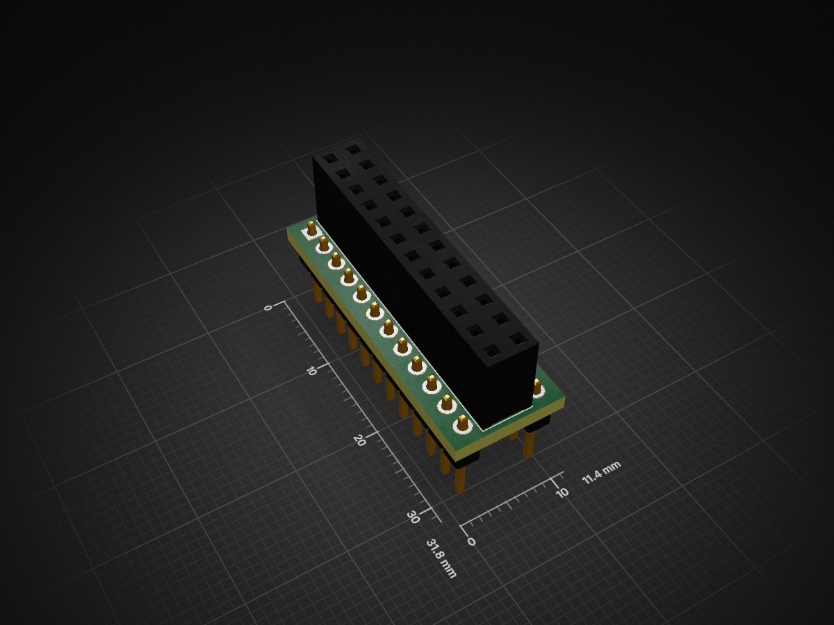
Hivee is an open-source printed circuit board by breadbee, from the breadbee/breadbee repository on GitHub, published under the GPL-3.0 licence. It is a 2-layer board of 11.4 × 31.8 mm with 3 parts on 24 nets, routed with 24 tracks and 0 vias.
It belongs with the computers and single-board computers and microcontroller boards boards of this library.
A very small, 32mm x 30mm, ARM Cortex A7 development board that costs about ~$10 to make in low quantities and can be assembled at home with a cheap hot air rework station. With a small adapter socket it can be mounted vertically in a standard breadboard.
The breadbee is based on a relatively unknown IP camera SoC, the MSC313E, from a company called MStar (now part of MediaTek as a subsidiary called SigmaStar). You might have never heard of MStar but you probably have one of their chips in your TV.
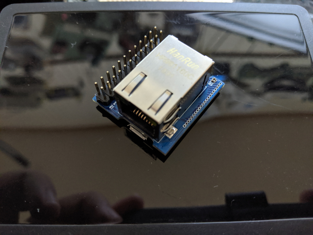
These are features that are working:
[0] MStar says it's 800MHz but their own cpufreq code says they clock it to 1GHz Clocking up to 1.1GHz works fine running dhrystone for hours but causes random lock ups if the spi nor controller and ethernet are fighting for bus access. [1] One UART is used by the serial console, two more are available via muxing.
The chip has a bunch of stuff in it that isn't supported yet:
It's full of flashy magic!
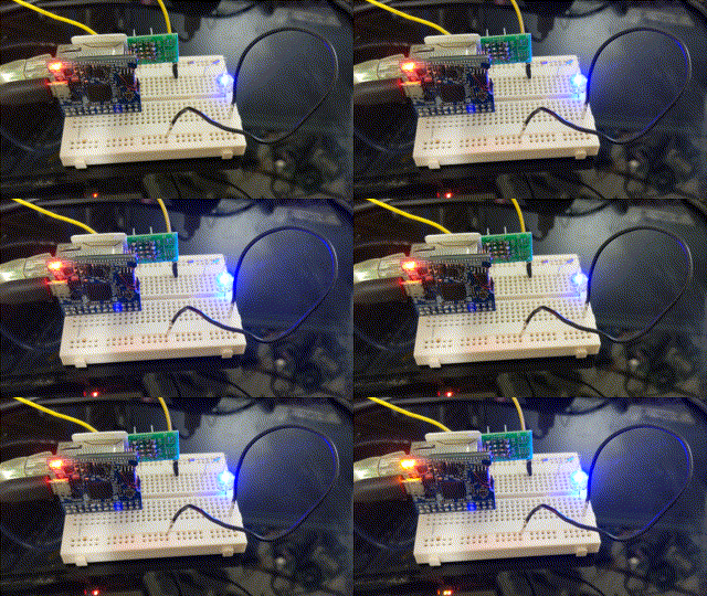
According to a Kyoritsu KEW 1062 inline with the vbus of a usb cable:
| state | Ethernet on | RTC wake | value |
|---|---|---|---|
| Booted idle | yes | N/A | 138mA |
| Booted idle | no | N/A | 113mA |
| Memory sleep | Yes | 12mA |
Networked microcontrollers are a disaster waiting to happen; Many solutions - even commercial ones - use LWIP as the TCP/IP stack with no intention of actually maintaining it, use relatively unknown TLS libraries because of lack of memory, have no memory protection, no isolation between the moving parts.
There are no solutions yet that can run a real OS like Linux that can be integrated by hobbyists into boards from cheap PCB vendors that don't have show stopping limitations. I.e. the AllWinner V3s is very similar to the SoC used here but it only has one SPI controller that is lost as soon as you put SPI NOR on it. The MSC313E has just enough of the usual microcontroller peripherals to make it useful, comes in a (relatively) easy to work with QFN package, is tiny and costs ~$4. It is a bit harder to integrate into your designs than a microcontroller that requires a single power supply but all of the information you would need to do so is right here. The schematic for the breadbee is incredibly simple.
There are single board computers out there that have more cores, more memory etc and are still around $10 but they are over kill for applications where even an ESP32 has enough horse power and they aren't usually something you can integrate into your project without reserving considerable space.
Why not? The MSC313E is a Cortex-A so getting Linux running from scratch was relatively simple. The peripherals are super weird in places but not totally insane.
The breadbee is meant to be a "minimum viable product" to get the ball rolling. It's impossible to write drivers for the SDIO controller or USB needed for WiFi without a platform to work on. Breadbee is that platform. Once SDIO works there will be an Ampak AP6212 based module to add wifi to breadbees and maybe a respin of the breadbee with the ethernet jack replaced with an Ampak module.
A simpler alternative consists in using an already supported USB-to-WiFi PCB module given that the breadbee's USB host controller already works fine. This project is .
If you ask very nicely and you are willing to do something like write a nice python library or flesh out drivers for the board it's possible you can have one of the prototype boards for FREE! Get in touch!
If you just want to buy one the intention is to put the board up on a crowd sourcing site at some point. When that happens that information will be here. crowdsupply will eventually be selling premade boards. This might take a while though.
If you want chips to integrate into your own projects and don't have contacts in Shenzhen to get them get in touch and we'll figure something out. If you want 2080 of them getting them isn't a problem. If you want one or two I have a small supply. If the crowd sourcing happens and there is enough money left to buy extra chips to distribute in more accessible ways I will. Since April 2020 chips have now also started to turn on up ebay.
The gerbers have been uploaded to OSH park (rev1) ready to order. OSH park (rev0)
Note that this is all in flux right at the moment. These repos are getting rebase'd fairly often.
There is a basic port of u-boot that so far take over from the MStar IPL and load a kernel from the SPI NOR, write it etc. See boot process below for more details.
https://github.com/fifteenhex/u-boot/tree/msc313
All of the above features work to some degree in the work tree. Mainlining is in progress but will take time. For more info please see the linux-chenxing.org page about mainlining.
Combines the u-boot and kernel above with a root filesystem and generates flashable images. There are some small pieces of a board configuration application called "beecfg" to setup pinmuxing etc.
https://github.com/fifteenhex/breadbee_buildroot
| interrupt | 5v tolerant | notes | alt functions | name | # | # | name | alt functions | notes | 5v tolerant | interrupt |
|---|---|---|---|---|---|---|---|---|---|---|---|
| +5v | 1 | 2 | +3v3 | ||||||||
| gnd | 3 | 4 | pm_gpio4 | [0] | yes | yes | |||||
| i2c1_scl | 5 | 6 | i2c1_sda | ||||||||
| yes | ej_tck, pwm4 | spi0_cz | 7 | 8 | spi0_ck | ej_tms, pwm5 | yes | ||||
| yes | ej_tdo, pwm6 | spi0_di | 9 | 10 | spi0_do | ej_tdi, pwm7 | yes | ||||
| yes | sar_gpio2 | 11 | 12 | sar_gpio3 | yes | ||||||
| yes | sar_gpio1 | 13 | 14 | sar_gpio0 | yes | ||||||
| yes | cs | spi0_cz, pwm0 | fuart_rx | 15 | 16 | fuart_tx | spi0_ck, pwm1 | clk | yes | ||
| yes | mosi, [1] | spi0_di, pwm2, uart1_rx | fuart_cts | 17 | 18 | fuart_rts | spi0_do, pwm3, uart1_tx | miso | yes | ||
| sr_io7 | 19 | 20 | sr_io6 | ||||||||
| sr_io5 | 21 | 22 | sr_io4 | ||||||||
| sr_io3 | 23 | 24 | sr_io2 |
0: This is a special pin that has to be explictly unlocked to be set. It seems to be intended for powering down the main CPU. It might move on rev1.
1 - When fuart is mux'd in it's also possible to mux'in uart1 and get a working rx only second uart here.
| name | # | alt functions | 5v tolerant | interrupt | notes |
|---|---|---|---|---|---|
| +3v3 | 1 | ||||
| sd_d3 | 2 | spi1_do | yes | miso | |
| sd_d2 | 3 | spi1_di | yes | mosi | |
| sd_d1 | 4 | spi1_ck | yes | clk | |
| sd_d0 | 5 | spi1_cz | yes | cs | |
| sd_cmd | 6 | yes | |||
| sd_clk | 7 | yes | |||
| pm_sd_cdz | 8 | yes | |||
| gnd | 9 | ||||
| +5v | 10 | ||||
| usb_dm | 11 | ||||
| usb_dp | 12 | ||||
| gnd | 13 | ||||
| sr_io15 | 14 | ||||
| sr_io14 | 15 | ||||
| sr_io13 | 16 | ||||
| sr_io12 | 17 | ||||
| sr_io11 | 18 | ||||
| sr_io10 | 19 | ||||
| sr_io9 | 20 | ||||
| sr_io8 | 21 |
JTAG is enabled at boot up on the spi0 pins by the u-boot SPL.
linux-chenxing has more info about mstar/sigmastar socs.
A nice blog entry from Willy about his experience building boards
| Qty | Value | Footprint | References |
|---|---|---|---|
| 2 | Conn_01x12_Male | Connector_PinHeader_2.54mm:PinHeader_1x12_P2.54mm_Vertical | J2, J3 |
| 1 | Conn_02x12_Odd_Even | Connector_PinSocket_2.54mm:PinSocket_2x12_P2.54mm_Vertical | J1 |
It measures 11.4 × 31.8 mm and has 2 copper layers, 1.6 mm thick.
3 parts. The full list of its parts is on this page, with links to each part's symbol and footprint where PCBKit's library has them.
From the breadbee/breadbee repository on GitHub, at the commit this page was made from: the board is hivee/hivee.kicad_pcb. PCBKit opens the board in the browser, with nothing to install.
Its repository publishes it under the GPL-3.0 licence: you may reuse it on that licence's terms (keep the author's notice, and for a copyleft licence share your changes alike).


hzeller/rpi-rgb-led-matrix
Controlling up to three chains of 64x64, 32x32, 16x32 or similar RGB LED displays using Raspberry Pi GPIO


atopile/atopile
Design circuit boards with code! ✨ Get software-like design reuse 🚀, validation, version control and collaboration in hardware; starting with electronics ⚡️


hackclub/sprig
🍃 Learn to code by making games in a JavaScript web-based game editor.