2 layers
SmartEggTimer
meierh/Embedded_System_Hands_On_I
All files related to the group project can be found in the Project folder. It contains the following parts of our project:
66 parts
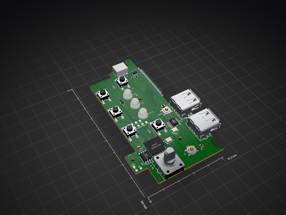
 brandonrc/das4-controller1
Open-source RP2350B replacement controller board for the Das Keyboard 4 Professional (KiCad 10)
Das4-controller is an open-source printed circuit board by brandonrc, from the brandonrc/das4-controller repository on GitHub, published under the MIT licence. It is a 4-layer board of 51.1 × 94 mm with 83 parts on 73 nets, routed with 921 tracks and 457 vias.
It is built around the RP2350B, W25Q128JVSIQ and CH334R, with the ME6211C33M5G-N and EC12E24204A2 among its other parts. Its parts include 37 capacitors, 10 resistors, 7 switches, 4 ICs and 4 connectors. It belongs with the keyboards and input boards and the RP2350 boards of this library.


An open-source replacement controller board for the Das Keyboard 4 Professional: same outline, same holes, same connectors, but with an RP2350B you can flash with your own firmware (pico-sdk today, KMK/CircuitPython, QMK once it supports the RP2350B). It keeps the two USB-A ports (as a USB 2.0 hub), the volume knob, the NUM/CAPS/SCROLL LEDs (now RGB, any colour) and the five buttons. Every button gets its own GPIO, so you can make them do whatever you like.
Status: ready to order after a final 1:1 fit print. Routed, DRC clean (0 unconnected, 0 real violations), with independent circuit and layout reviews, a check against Raspberry Pi's RP2350 design guide, and a firmware build for this pinout. See docs/plan.md.
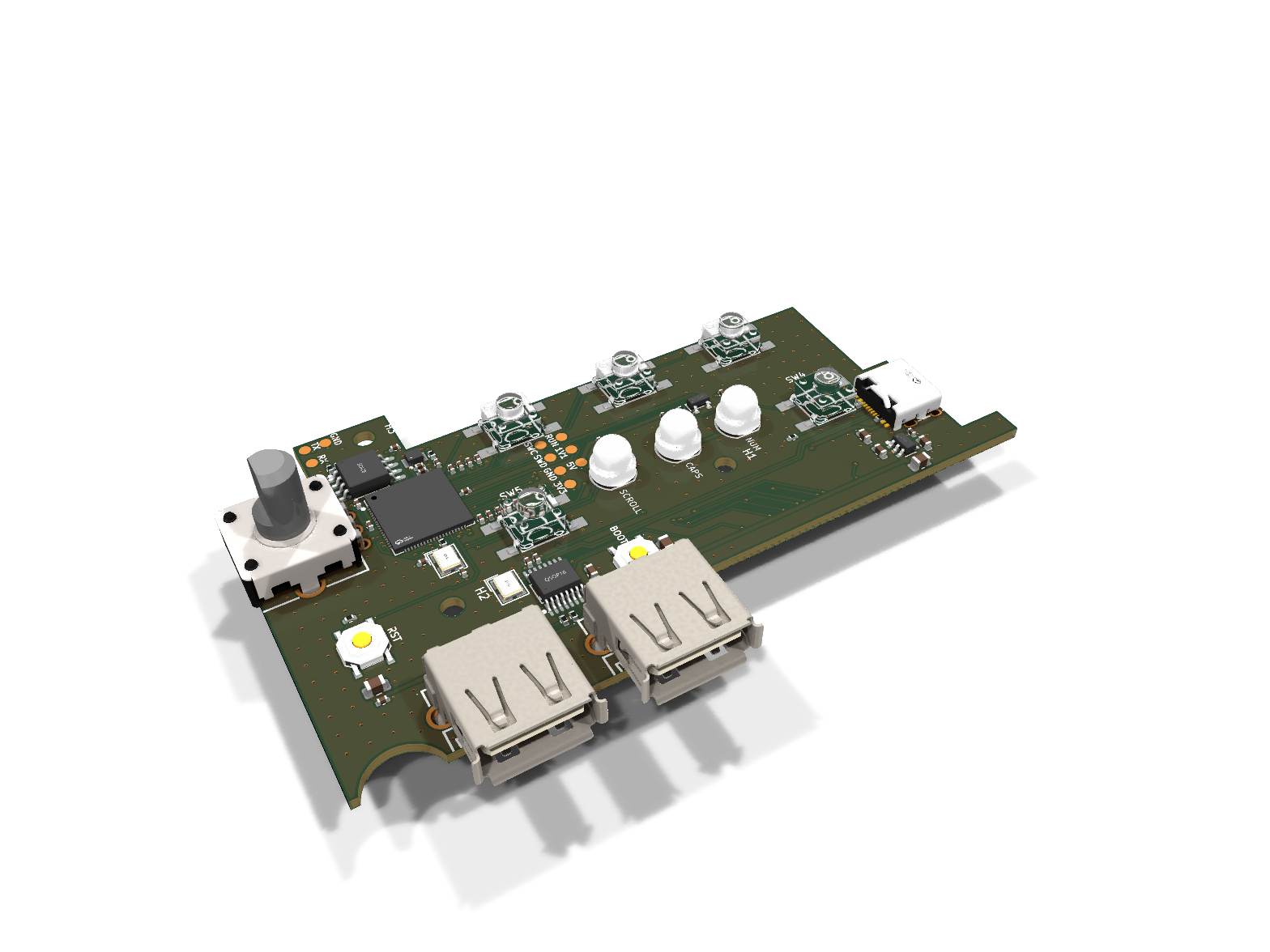
| Top | Bottom |
|---|---|
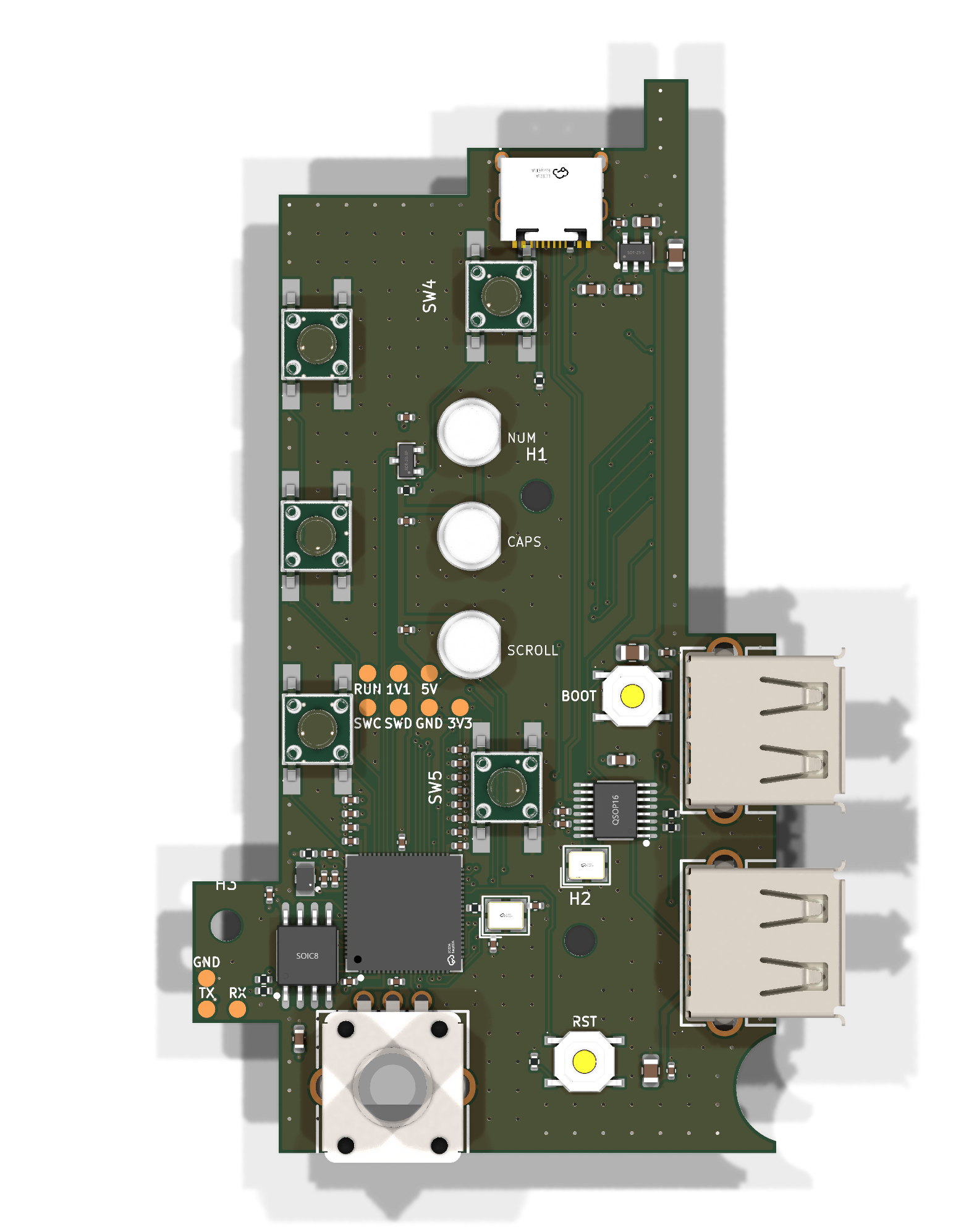 | 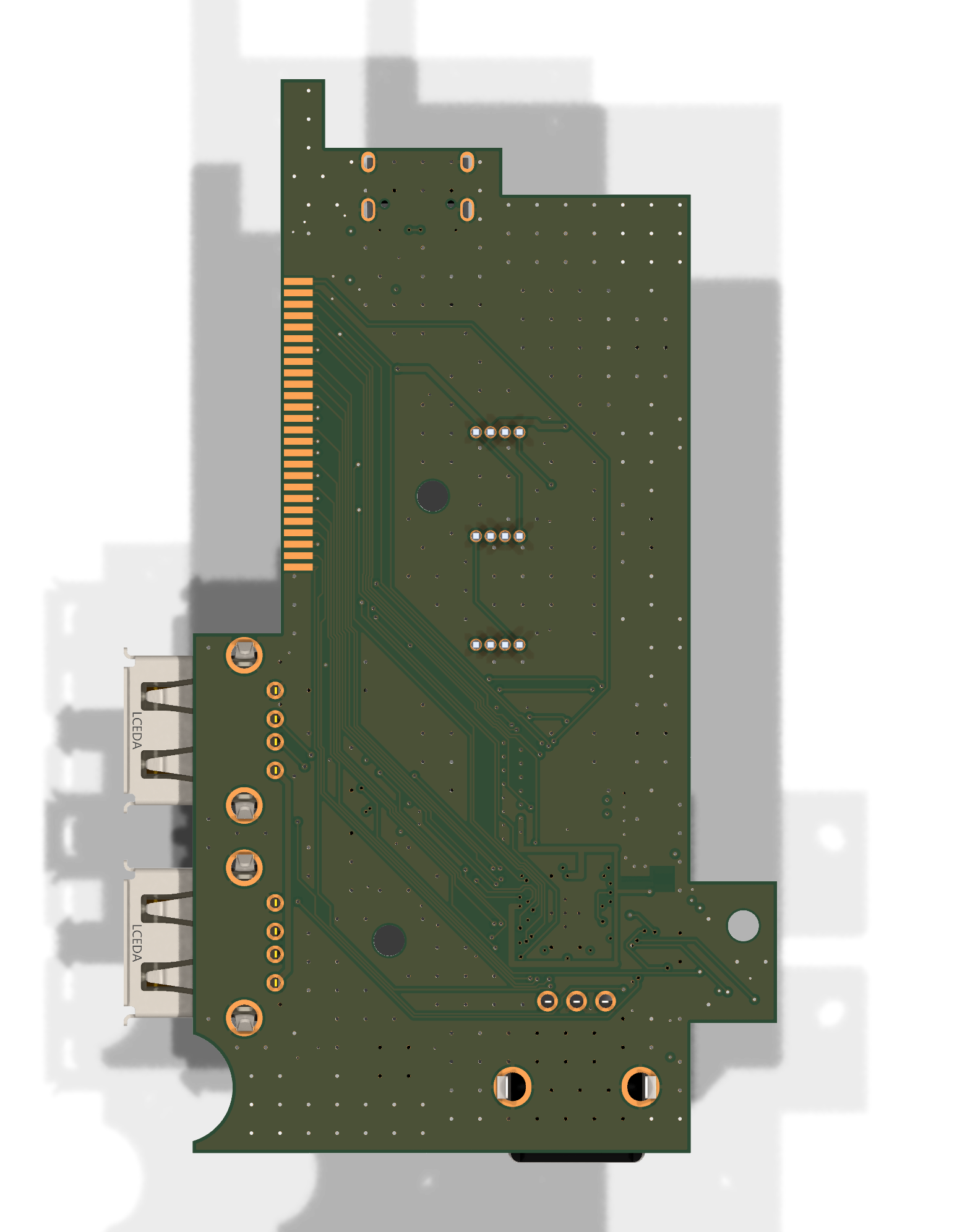 |
hardware/
  circuit/das4.py                          the circuit (SKiDL)
  das4-controller.net                      netlist generated from it
  das4-controller.kicad_pro / .kicad_pcb   KiCad 10 project (board generated from the netlist)
  lib/jlc.*                                JLCPCB part symbols, footprints and 3D models (easyeda2kicad)
  lib/das4.pretty                          our own footprints (J4 flex solder pads)
  scripts/gen_board.py                     outline, measured positions, placement, silkscreen
  scripts/critical.py                      hand-drawn critical nets + keep-outs (RP2350 regulator, USB pair, crystal...)
  scripts/route.py, route_best.py          autorouting (Freerouting) + cleanup + GND stitching, best of 6 runs
  scripts/pretest.py, check_layout.py      pre-route DRC of the hand layout; post-route checks
  scripts/jlc_fab.py                       JLCPCB gerber zip, BOM and CPL
  scripts/jlc.py                           search JLCPCB's parts library (no login)
  scripts/bom.py                           docs/bom.md with live stock
docs/                                      notes, plan, reviews, renders, fit-check print
firmware/bringup/ pico-sdk + TinyUSB bring-up firmware for this pinoutThe tools come from the KiBot/KiCad container
ghcr.io/inti-cmnb/kicad10_auto_full,
which is also what CI runs.
# one-time: create the container
distrobox create --name pcb --image ghcr.io/inti-cmnb/kicad10_auto_full:1.9.1-1_k10.0.5_d13.2_b4.2.4LTS

distrobox enter pcb -- make pretest       # quick DRC of just the hand layout (run before routing)
distrobox enter pcb -- make board route   # circuit -> netlist -> placed board -> autorouted (~25 min)
distrobox enter pcb -- make check         # post-route checks DRC can't do
distrobox enter pcb -- make docs drc fab  # renders, fit-check PDF, DRC, JLCPCB files (don't rebuild the board)
distrobox enter pcb -- make bom      # refresh docs/bom.md with live JLCPCB stock
Or use Docker directly:
docker run --rm -v $PWD:/w -w /w ghcr.io/inti-cmnb/kicad10_auto_full:1.9.1-1_k10.0.5_d13.2_b4.2.4LTS make.
Open hardware/das4-controller.kicad_pro in KiCad 10 to look around.
Note: the board file is generated: make board rebuilds it (unrouted)
from the circuit and gen_board.py, and make route routes it. Edit those,
not the .kicad_pcb, or your changes get overwritten.
distrobox enter pcb -- make fab # -> build/jlcpcb/: gerber zip, bom.csv, cpl.csvbom.csv and cpl.csv, and check the placement preview:
rotations, and L1's white dot on the +1V1 pad next to C165 (details in docs/design.md).make fab names the zip ...-UNROUTED-quote-only if the board has no traces yet.
MIT, see LICENSE. Not affiliated with Das Keyboard / Metadot.
| Qty | Value | Footprint | References |
|---|---|---|---|
| 22 | 100n | C_0402_1005Metric | C10, C12, C105, C110, C115, C124, C129, C132, C141, C150, C151, C159, C160, C168, C169, C176 +6 |
| 10 | TestPoint | TestPoint_Pad_D1.5mm | TP1, TP2, TP3, TP4, TP5, TP6, TP7, TP8, TP9, TP10 |
| 5 | 10u | C_0603_1608Metric | C3, C4, C5, C8, C190 |
| 4 | 1k | R_0402_1005Metric | R10, R231, R302, R303 |
| 4 | 4.7u | C_0402_1005Metric | C161, C164, C165, C166 |
| 3 | 22u | C_0805_2012Metric | C1, C9, C11 |
| 3 | MountingHole_2.7mm_M2.5 | MountingHole_2.7mm_M2.5 | H1, H2, H3 |
| 2 | 12MHz | CRYSTAL-SMD_4P-L3.2-W2.5-BL | Y1, Y2 |
| 2 | 15p | C_0402_1005Metric | C230, C231 |
| 2 | 22 | R_0402_1005Metric | R266, R267 |
| 2 | 5.1k | R_0402_1005Metric | R1, R2 |
| 1 | 10k | R_0402_1005Metric | R301 |
| 1 | 1u | C_0402_1005Metric | C6 |
| 1 | 2N7002 | SOT-23-3_L2.9-W1.3-P1.90-LS2.4-BR | Q1 |
| 1 | 3.3uH | IND-SMD_L2.0-W1.6_AOTA-B201610S3R3-101-T | L1 |
| 1 | 33 | R_0402_1005Metric | R161 |
| 1 | BOOTSEL | SW-SMD_4P-L5.1-W5.1-P3.70-LS6.5-TL_H1.5 | SW6 |
| 1 | Button 1 | SW-SMD_4P-L6.0-W6.0-P4.50-LS9.0_H5.0 | SW1 |
| 1 | Button 2 | SW-SMD_4P-L6.0-W6.0-P4.50-LS9.0_H5.0 | SW2 |
| 1 | Button 3 | SW-SMD_4P-L6.0-W6.0-P4.50-LS9.0_H5.0 | SW3 |
| 1 | Button 4 | SW-SMD_4P-L6.0-W6.0-P4.50-LS9.0_H5.0 | SW4 |
| 1 | Button 5 | SW-SMD_4P-L6.0-W6.0-P4.50-LS9.0_H5.0 | SW5 |
| 1 | CAPS (RGB) | LED-TH_4P-BD5.8-P1.27_WS2812D-F5-12MA-C1 | D2 |
| 1 | CH334R | QSOP-16_L4.9-W3.9-P0.64-LS6.0-BL | U2 |
| 1 | EC12E24204A2 | SW-TH_EC12E24204A2 | ENC1 |
| 1 | Key matrix flex | FPC_Solder_1x26_P1.00mm | J4 |
| 1 | ME6211C33M5G-N | SOT-23-5_L3.0-W1.7-P0.95-LS2.8-BL | U4 |
| 1 | NUM (RGB) | LED-TH_4P-BD5.8-P1.27_WS2812D-F5-12MA-C1 | D1 |
| 1 | RESET | SW-SMD_4P-L5.1-W5.1-P3.70-LS6.5-TL_H1.5 | SW7 |
| 1 | RP2350B | QFN-80_L10.0-W10.0-P0.40-TL-EP3.4 | U1 |
| 1 | SCROLL (RGB) | LED-TH_4P-BD5.8-P1.27_WS2812D-F5-12MA-C1 | D3 |
| 1 | USB-A 1 | USB-A-TH_AF-WJDG | J2 |
| 1 | USB-A 2 | USB-A-TH_AF-WJDG | J3 |
| 1 | USB-C | USB-C_SMD-TYPE-C-31-M-12_1 | J1 |
| 1 | W25Q128JVS | SOIC-8_L5.3-W5.3-P1.27-LS8.0-BL | U3 |
It measures 51.1 × 94 mm and has 4 copper layers, 1.6 mm thick.
83 parts, built around the RP2350B, W25Q128JVSIQ, CH334R and ME6211C33M5G-N. The full list of its parts is on this page, with links to each part's symbol and footprint where PCBKit's library has them.
From the brandonrc/das4-controller repository on GitHub, at the commit this page was made from: the board is hardware/das4-controller.kicad_pcb. PCBKit opens the board in the browser, with nothing to install.
Its repository publishes it under the MIT licence: you may reuse it on that licence's terms (keep the author's notice, and for a copyleft licence share your changes alike).
meierh/Embedded_System_Hands_On_I
All files related to the group project can be found in the Project folder. It contains the following parts of our project:

gschuurman/android_vendor_gschuurman_vehicle_interfaces
vehicle interfaces for android automotive for a custom headunit


OpenStickCommunity/Hardware
A collection of hardware designs by members of the OpenStickCommunity