2 layers116.8 × 30 mm
Type d
google/mozc-devices
Circuit diagrams and firmware source code for Gboard DIY keyboards
14 parts3kApache-2.0

 brainstorm/915Mhz2
915Mhz matching jig experiments
Rf matching is an open-source printed circuit board by brainstorm, from the brainstorm/915Mhz repository on GitHub. It is a 2-layer board of 45.7 × 47.5 mm with 14 parts on 13 nets, routed with 57 tracks and 731 vias.
It is built around the SF2098E. Its parts include 7 connectors, 3 capacitors, 2 resistors and 2 ICs. It belongs with the radio and wireless boards of this library.
This is an experiment with a 915Mhz LoRa module and SAW filters as a substitute for discrete components. The original raison d'être of this repository is my personal outrage after seeing the following $100 evaluation board for the PE4259:
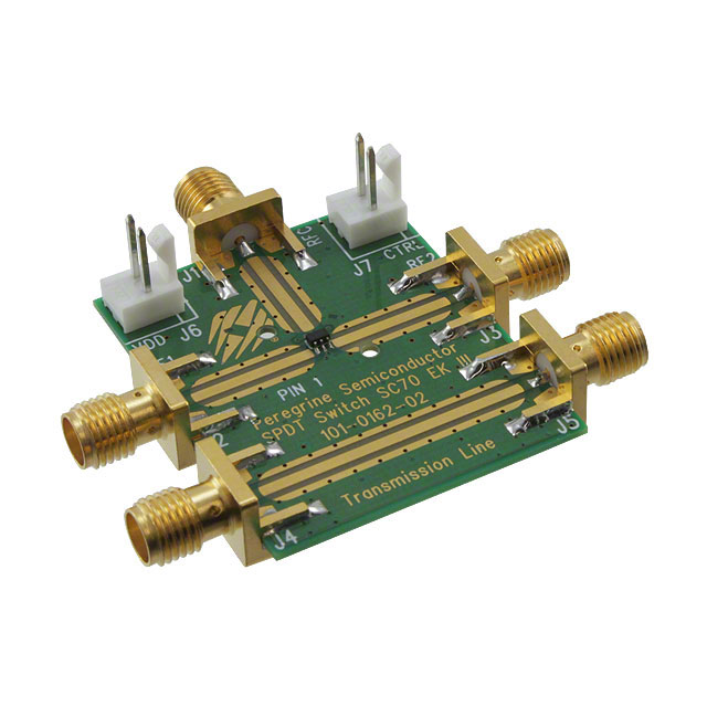
And indeed, AppliedCarbon from OSHPark also thought so and designed a smaller PCB.
Gold tracks and pads, many vias and proper RF engineering, sure, but $100 plus shipping? Let's see how the homemade way works in comparison? On the master branch of this repository, I'm putting together a board with the RF switch and the SAW filter (will be using a 915 Mhz sf2098e "low insertion loss" SAW filter, no frills design for now. I might put the vias in place if needed in the future and compare performance/loss and the accompanying S parameters.
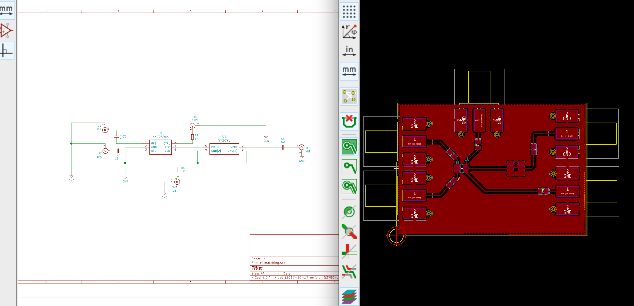
But since the approach above might not be modular enough for my testing purposes (thanks Chris), I've forked that layout into two branches:
$ git branch -a
* master
  rf_switch_only
  saw_filter_only
Here's how each of those look like at the moment of writing this, let's play "spot the differences", shall we?:
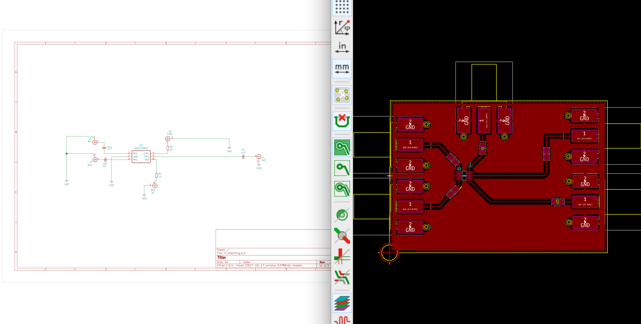
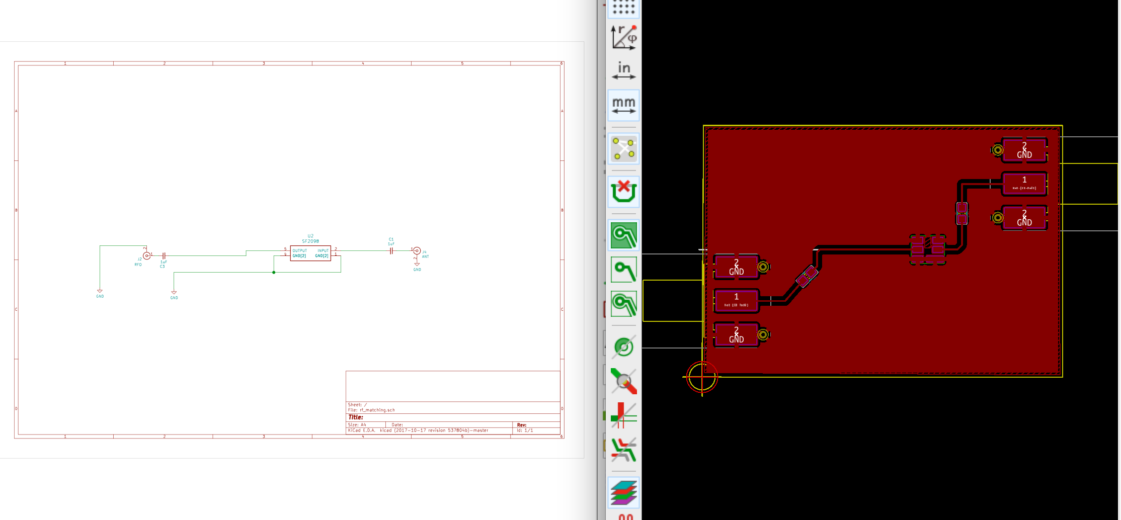
Now, as with the Instructables Carvey Board project, I've generated some G-Code (under the homefab subdirectory) with FlatCam to carve those board at home, wish me luck with the spectrum analyzers and followup testing!
Alternatively, there's a .zip under homefab, containing the ready-to-send gerbers to i.e Seed Studios or any other PCB manufacturer. Here's the latest iteration of the rf matching board on master:
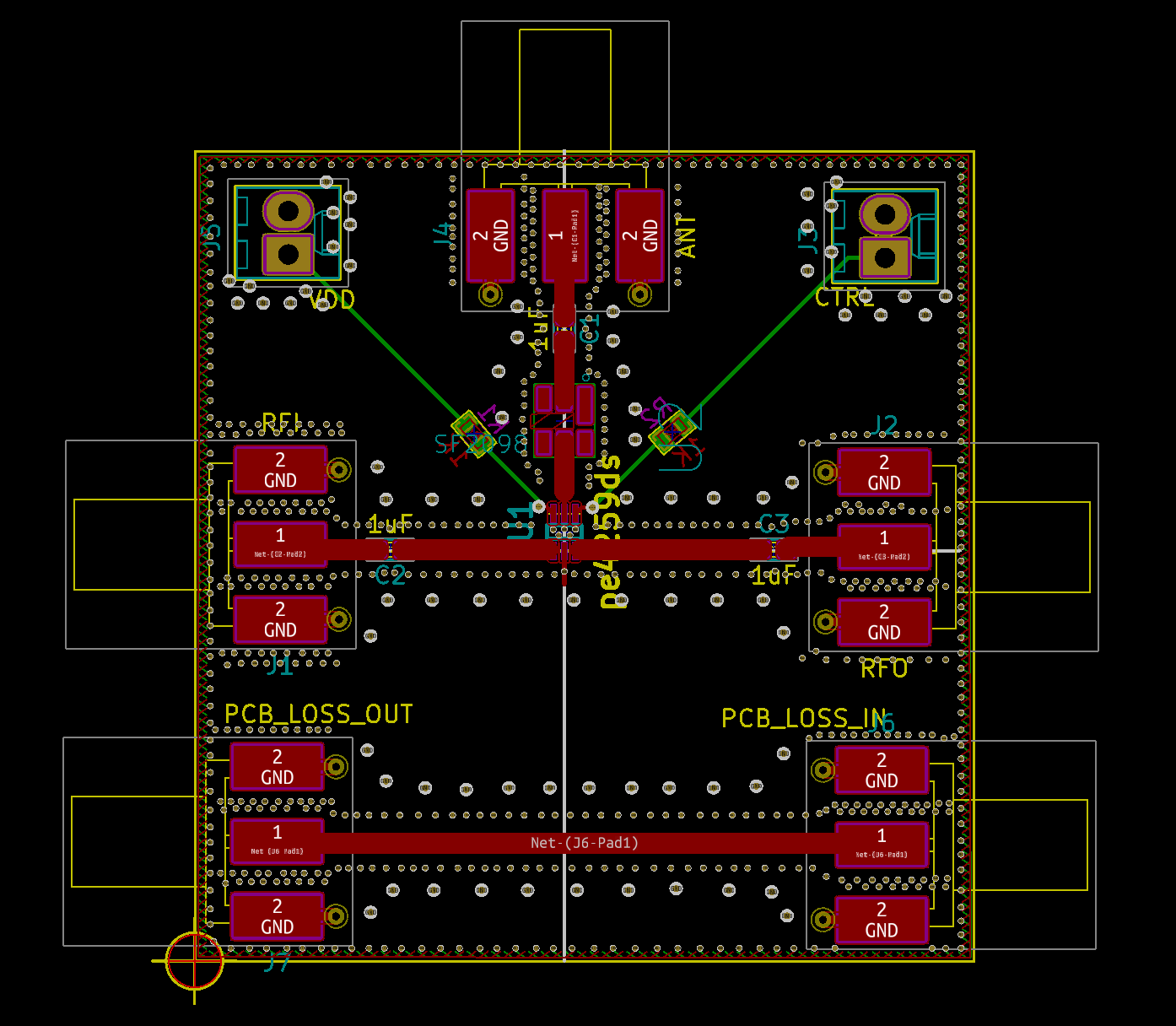
| Qty | Value | Footprint | References |
|---|---|---|---|
| 3 | 1uF | KiCad/Capacitors_SMD.pretty:C_0603 | C1, C2, C3 |
| 2 | 1K | KiCad/Resistors_SMD.pretty:R_0603 | R1, R2 |
| 1 | ANT | KiCad/Connectors_Molex.pretty:Molex_SMA_Jack_Edge_Mount | J4 |
| 1 | CTRL | KiCad/Connectors_Molex.pretty:Molex_KK-6410-02_02x2.54mm_Straight | J3 |
| 1 | PCB_LOSS_IN | KiCad/Connectors_Molex.pretty:Molex_SMA_Jack_Edge_Mount | J6 |
| 1 | PCB_LOSS_OUT | KiCad/Connectors_Molex.pretty:Molex_SMA_Jack_Edge_Mount | J7 |
| 1 | RFI | KiCad/Connectors_Molex.pretty:Molex_SMA_Jack_Edge_Mount | J1 |
| 1 | RFO | KiCad/Connectors_Molex.pretty:Molex_SMA_Jack_Edge_Mount | J2 |
| 1 | SF2098 | SON120P300X300X110-6N:SON120P300X300X110-6N | U2 |
| 1 | VDD | KiCad/Connectors_Molex.pretty:Molex_KK-6410-02_02x2.54mm_Straight | J5 |
| 1 | pe4259ds | OLIMEX/KiCAD/KiCAD_Footprints/OLIMEX_IC-FP.pretty:SC70-6_Pitch-0.65_2.00x2.10x1.00mm | U1 |
It measures 45.7 × 47.5 mm and has 2 copper layers, 1.6 mm thick.
14 parts, built around the SF2098E. The full list of its parts is on this page, with links to each part's symbol and footprint where PCBKit's library has them.
From the brainstorm/915Mhz repository on GitHub, at the commit this page was made from: the board is rf_matching.kicad_pcb. PCBKit opens the board in the browser, with nothing to install.
Its repository states no licence, so its author keeps all rights: ask brainstorm before reusing the design.
google/mozc-devices
Circuit diagrams and firmware source code for Gboard DIY keyboards


hackclub/OnBoard
💡 Join 1,000 teenagers and make your first PCB with a $100 grant!


Twotoz/C5VRX
Ultra-minimal, zero-CPU 5.8 GHz analog FPV video receiver using ESP32-C5 Wi-Fi 6 PHY MODEM_DIAG, BitScrambler WBFM demodulation & resistor DAC CVBS

