

2 layers60 × 50 mm
Driver wide
brainsmoke/leddriver3d
Renamed from esp32leddriver because it also contains code and PCBs for other MCUs
73 parts11

 brainsmoke/leddriver3d11
Renamed from esp32leddriver because it also contains code and PCBs for other MCUs
Driver aluball v1 is an open-source printed circuit board by brainsmoke, from the brainsmoke/leddriver3d repository on GitHub. It is a 2-layer board of 82.8 × 70.7 mm with 29 parts on 56 nets, routed with 314 tracks and 73 vias.
It is built around the ESP32-WROVER and AO3400. Its parts include 9 connectors, 6 capacitors, 6 resistors, 3 ICs and 2 transistors. It belongs with the lEDs and displays boards and the ESP32 and STM32 boards of this library.
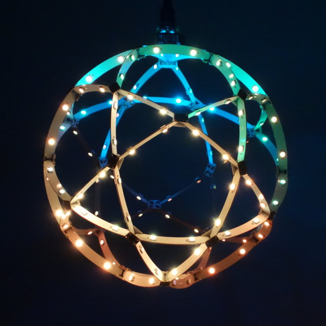
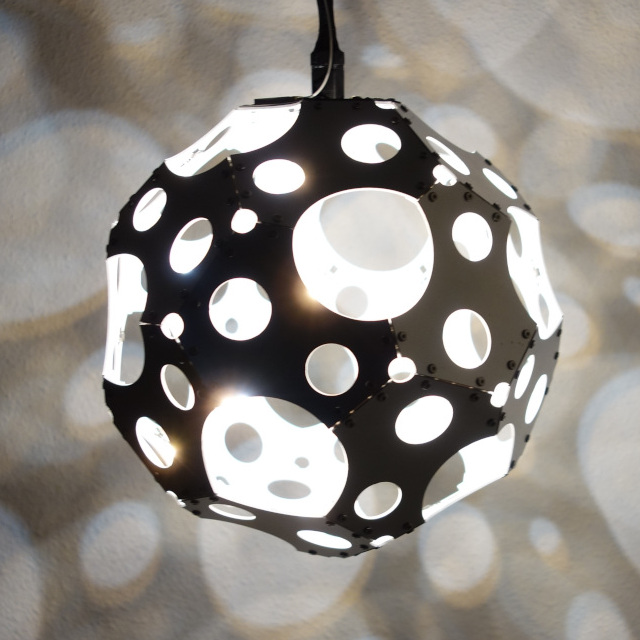
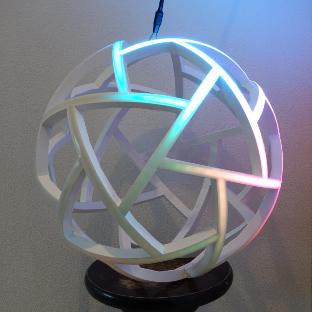
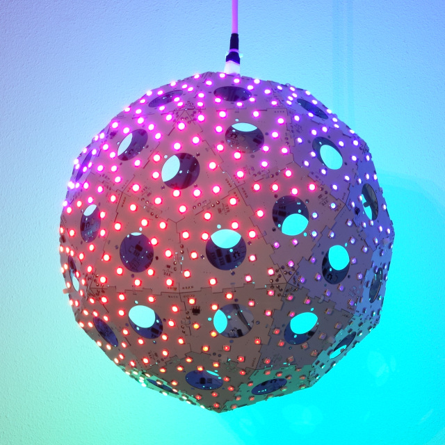
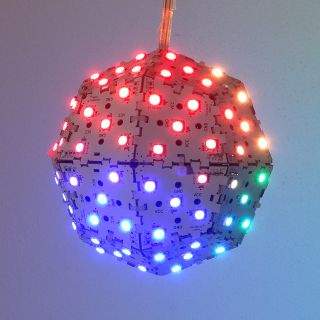
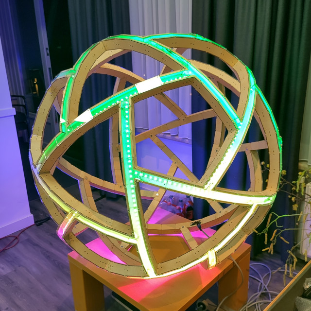
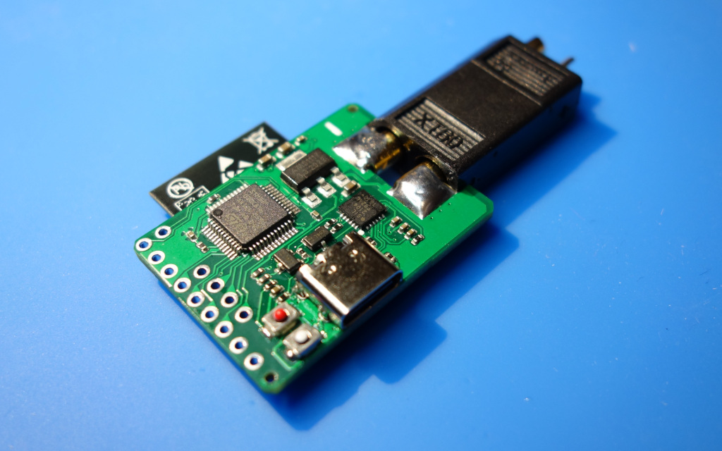
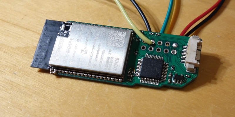
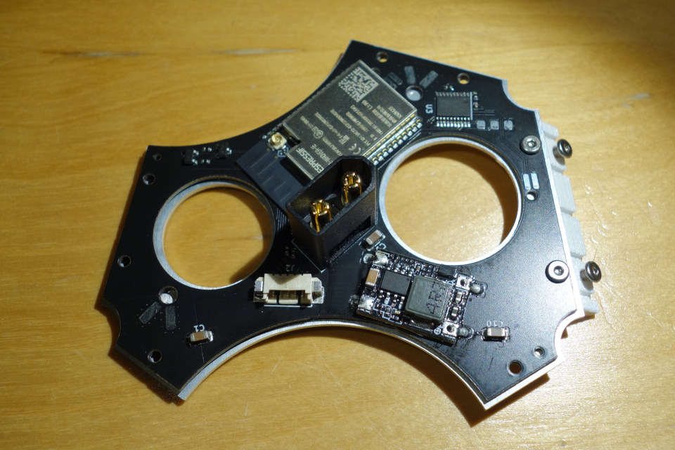
   programming &
  micropython REPL
         ||
     .--------.
     |  usb   |
     |   to   |  unified codebase       project specific firmware
     | serial |    /                            \
     '--------'   /                              \
         ||      /   standardized protocol        \
   .--------------.            |                  _____________.--
   |  ESP32-D0WD  |          (UART)              |             |-- multiple LED strands
   |   8M PSRAM   |-- 16bit/color LED frames --> |  STM32F0XX  |-- (temporal dithered)
   |  16M FLASH   |                              |_____________|--
'--------------' '--firmware/esp32/Running micropython
60 FPS 16bit/color (48bit) animation with some routines written in C for speed.
Animations use 3D-coordinates of the LEDs, as well as the direction they're pointing at
Gamma correction & support for multiple LED orderings.
Cached animation frames to prevent garbage collection hiccups
Web interface (HTTPS capable, but no automatic cert. updates)
firmware/stm32/Sending a frame: ( [16 bit brightness]* [ FF FF FF F0 ] )*
Brightness must be little endian integers in the (inclusive) range [0 .. 0xFF00]
[ FF FF FF F0 ] is an end of frame marker and allows the protocol to synchronize
in the event of an uneven number of bytes being written to the serial port
The firmware is completely agnostic about the color ordering.
Some of the following firmwares allow for tuning of the pulse interval:
( [16 bit number]* [ FF FF FF F3 ] )*
The given number is the number of cycles outputting a byte should take. (Useful for increasing the FPS and thus improving temporal dithering.
dither16.binRead in 16bit/color data in, drive 8 ws2812 LED strips in parallel
strip4.binRead in 16bit/color data in, drive 4 ws2812 LED strips in parallel
strip5.binRead in 16bit/color data in, drive 5 ws2812 LED strips in parallel, Supports tuning the pulse interval.
relayball.binRead in 16bit/color data in, drive 4 circuit-routed ws2812 LED meshes.
Small LED strands are connected through PADAUK based relay-chips
(firmware/pdk/relay/) that use in-band messages to build up routing
circuits.
uartball16.binDrives up-to 8 busses with PADAUK based LED drivers which read 38400 baud
uart. firmware/pdk/softpwm/
dither8.binOlder code using a different input protocol, reads 8bit/color data & transforms this to 16 bit colors after gamma correction
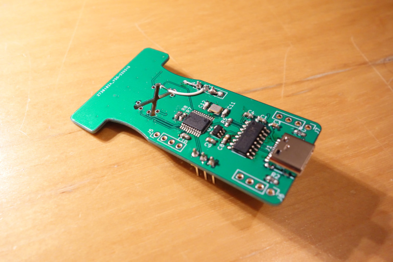
jitter_timer.binTester for PADAUK ws2812 relay chips. firmware/pdk/relay/
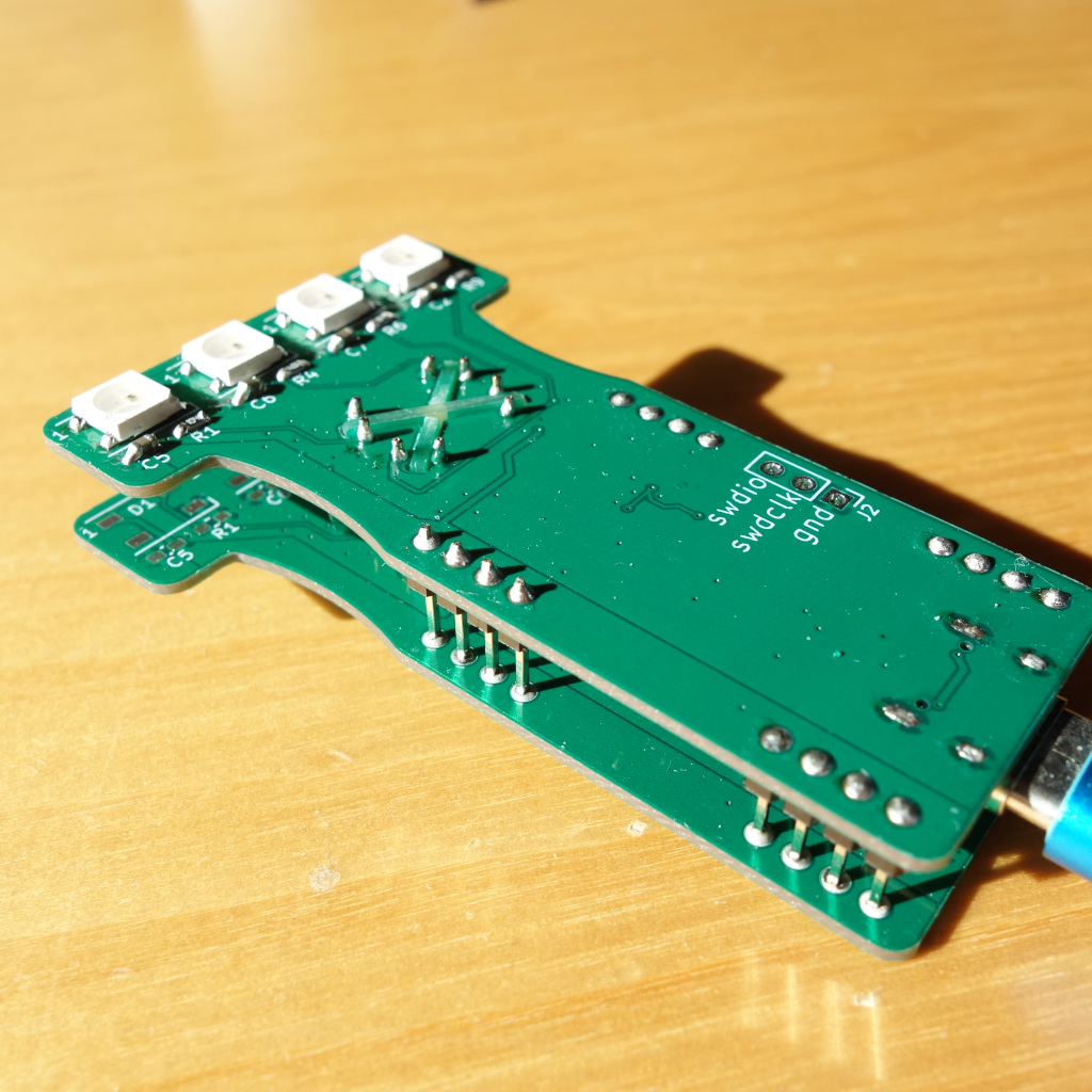
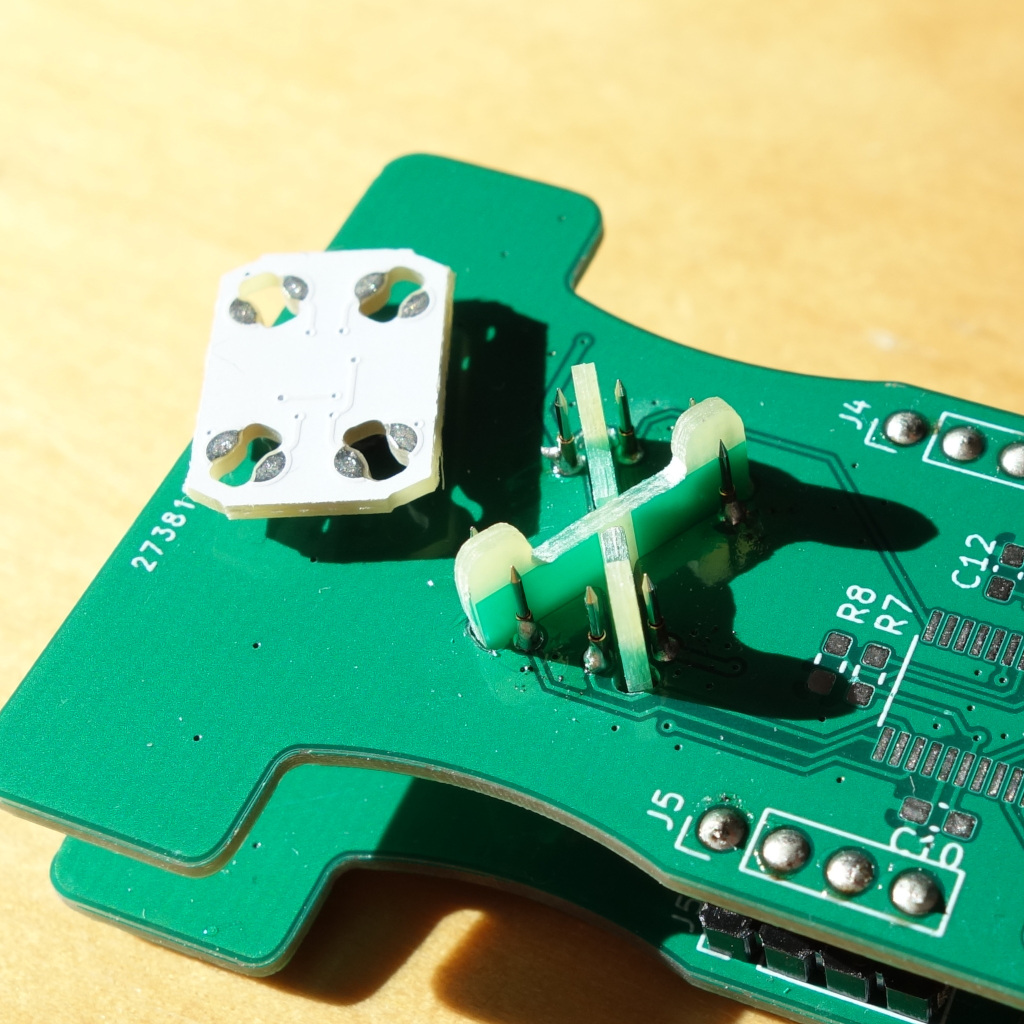
Tests for functionality and measures the clock speed deviation (for binning).
timing_experiment.binDynamically adjust the T1H and T1L intervals from the ws2812 protocol to
test its limits.
| Qty | Value | Footprint | References |
|---|---|---|---|
| 6 | 10k | Resistor_SMD:R_0402_1005Metric | R3, R4, R5, R6, R7, R11 |
| 4 | Conn_01x01_Male | outline:solderpad1 | J6, J7, J8, J9 |
| 3 | 10uF | Capacitor_SMD:C_1206_3216Metric | C1, C9, C10 |
| 2 | 100nF | Capacitor_SMD:C_0402_1005Metric | C5, C8 |
| 2 | AO3400 | Package_TO_SOT_SMD:SOT-23 | Q1, Q2 |
| 2 | Conn_01x02_Male | Connector_PinHeader_2.54mm:PinHeader_1x02_P2.54mm_Vertical | J3, J4 |
| 1 | outline:outline | ||
| 1 | 1uF | Capacitor_SMD:C_0402_1005Metric | C7 |
| 1 | Conn_01x02_Male | outline:xt60-pcb | J1 |
| 1 | Conn_01x03_Male | Connector_PinHeader_2.54mm:PinHeader_1x03_P2.54mm_Vertical | J5 |
| 1 | Conn_01x05_Male | Connector_Molex:Molex_PicoBlade_53261-0571_1x05-1MP_P1.25mm_Horizontal | J2 |
| 1 | ESP32-WROVER | esp32-wrover:XCVR_ESP32-WROVER | U1 |
| 1 | STM32F030F4Px | Package_SO:TSSOP-20_4.4x6.5mm_P0.65mm | U3 |
| 1 | dcdc3a-12.5x17.4 | outline:dcdc3a-12.5x17.4 | U2 |
The 27 most common of 29 parts.
It measures 82.8 × 70.7 mm and has 2 copper layers, 1.6 mm thick.
29 parts, built around the ESP32-WROVER and AO3400. The full list of its parts is on this page, with links to each part's symbol and footprint where PCBKit's library has them.
From the brainsmoke/leddriver3d repository on GitHub, at the commit this page was made from: the board is pcb/driver_aluball_v1/pcb.kicad_pcb and its schematic pcb/driver_aluball_v1/pcb.kicad_sch. PCBKit opens the board in the browser, with nothing to install.
Its repository states no licence, so its author keeps all rights: ask brainsmoke before reusing the design.
brainsmoke/leddriver3d
Renamed from esp32leddriver because it also contains code and PCBs for other MCUs

brainsmoke/leddriver3d
Renamed from esp32leddriver because it also contains code and PCBs for other MCUs

brainsmoke/leddriver3d
Renamed from esp32leddriver because it also contains code and PCBs for other MCUs

brainsmoke/leddriver3d
Renamed from esp32leddriver because it also contains code and PCBs for other MCUs

brainsmoke/leddriver3d
Renamed from esp32leddriver because it also contains code and PCBs for other MCUs

brainsmoke/leddriver3d
Renamed from esp32leddriver because it also contains code and PCBs for other MCUs

brainsmoke/leddriver3d
Renamed from esp32leddriver because it also contains code and PCBs for other MCUs

brainsmoke/leddriver3d
Renamed from esp32leddriver because it also contains code and PCBs for other MCUs

brainsmoke/leddriver3d
Renamed from esp32leddriver because it also contains code and PCBs for other MCUs

brainsmoke/leddriver3d
Renamed from esp32leddriver because it also contains code and PCBs for other MCUs

brainsmoke/leddriver3d
Renamed from esp32leddriver because it also contains code and PCBs for other MCUs

brainsmoke/leddriver3d
Renamed from esp32leddriver because it also contains code and PCBs for other MCUs

shaun-lloyd/dev-ardupilot-obal
ArduPi is an open hardware Raspberry Pi hat to run Ardupilot.

ctag-fh-kiel/ctag-tbd
CTAG TBD >>to be determined<< an extendible open source Eurorack sound module


ctag-fh-kiel/esp32-eurorack-audio
Open source eurorack audio module based on ESP32

lucysrausch/sony-scopeman
Hardware Design files of a replacement mainboard for the Sony Watchman FD-10. This turns it into a bluetooth and WiFi-enabled vector display.

kbx81/ClimateSprinklerController
ESP32-based climate and sprinkler controller for use with ESPHome

SolderedElectronics/Soldered-Inkplate-10-hardware-design
Hardware design, BOM, gerbers and 3D files for Soldered-Inkplate-10 designed by Soldered Electronics.

har-in-air/ESP32_WROVER_BREAKOUT
Breadboard compatible breakout PCB for ESP32-WROVER with TPS82140 power supply