2 layers96 × 92 mm
Roller shutter controller
swanseahackspace/roller-shutter-controller
RFID interface board for Eurodrive Eurokit-3 roller shutter controllers or similar, based on Lolin C3 Mini
36 partsGPL-3.0

 bradport02/Half-Bridge-Motor-Controller
4-layer half-bridge motor controller (120 A peak / 40 A continuous, 24 V) designed to replace an off-the-shelf controller on a GreenPower electric race car. KiCad schematic + PCB, isolated gate drive, I²C temperature monitoring.
Half Bridge Motor Controller is an open-source printed circuit board by bradport02, from the bradport02/Half-Bridge-Motor-Controller repository on GitHub. It is a 4-layer board of 142 × 73 mm with 87 parts on 48 nets, routed with 367 tracks and 661 vias.
It is built around the TSR 1-24120, UCC21520ADW and ACSL-6400-50TE, with the UA78M05IDCY, V8PAL45HM3_A/I and IXFH120N20P among its other parts. Its parts include 31 resistors, 22 capacitors, 14 diodes, 6 ICs and 5 connectors. It belongs with the robots and motor control and interfaces and adapters boards of this library.


A custom half-bridge motor controller designed for a GreenPower electric race car, built for the Driven Electric Student Automotive Competition (ESAC) team. Designed to replace the team's off-the-shelf PORTER-10 controller, which limits continuous current to ~10-20 A.
Status: design complete (schematic + 4-layer KiCad PCB), not yet fabricated or bench-tested.
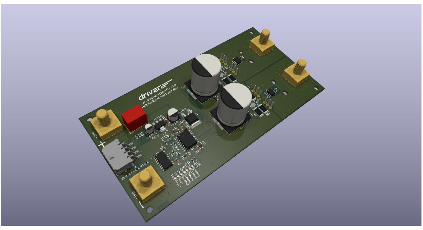 3D render from KiCad — board has not yet been manufactured.
Off-the-shelf controllers like the PORTER-10 are built for short current bursts and settle around 10-20 A continuous, which limits both acceleration off the line and sustained top speed. The goal was a controller capable of ~40 A continuous with a 120 A peak, giving the team a faster, more efficient motor drive and a platform that can be extended to regenerative braking in future.
The power stage is built around IRFB7440PbF N-channel MOSFETs (120 A rated), driven by a UCC21520 dual-channel gate driver. The UCC21520 takes PWM and control signals from a microcontroller and provides reinforced isolation between the low-voltage logic and the high-voltage power stage - protecting the control electronics from the transients typical of motor-drive environments. Its drive strength (4 A source / 6 A sink) is sized for fast, low-loss switching of the MOSFETs, and its programmable dead-time prevents shoot-through between high and low side.
Control interface:
Signal isolation is handled by an ACSL-6400-50TE optocoupler for additional noise immunity.
Two LM75 I²C temperature sensors monitor high-side and low-side MOSFET temperature, each with a programmable threshold that drives a status LED. The board has an onboard LED bank showing signal presence (PWM1/PWM2/Enable) and temperature-fault state at a glance.
Known open item: race telemetry shows battery voltage dropping below the TSR-1-24120's 15 V regulation floor during operation, which would drop the 12 V (and consequently 5 V) rail. A 12 V input pin is provided on the main connector as a workaround, but an external boost/always-available 12 V supply is the proposed fix and hasn't been implemented on this revision.
Four-layer stack-up:
Specified for 2 oz copper on the outer layers for thermal dissipation, with extensive thermal vias. MOSFETs are oriented facing away from the board so they can be mounted to an external heatsink (as on the PORTER-10) rather than relying on the PCB alone for cooling.
Designed in KiCad across two schematic sheets — Motor Controller and Power & Signals — split for readability.
This revision has no reverse-polarity protection. This was a deliberate decision agreed with the ESAC team: the added complexity of full reverse-polarity protection at this current rating wasn't considered justified for this revision. BAT+ and BAT- are clearly marked on the silkscreen; correct wiring is required.
Estimated production cost: ~£90/unit (~£45 components, ~£45 PCB manufacture via JLCPCB). See the BOM for full component-level pricing.
Power electronics design (MOSFET half-bridge, gate-drive isolation), 4-layer PCB design for high-current/thermal applications (KiCad), automotive/motorsport 12–24 V system design, I²C sensor integration, and BOM/cost engineering for a real production target.
Bradley Port — Designed for the Driven Electric Student Automotive Competition team.
| Qty | Value | Footprint | References |
|---|---|---|---|
| 9 | 100n | Capacitor_SMD:C_0603_1608Metric_Pad1.08x0.95mm_HandSolder | C1, C2, C7, C10, C13, C17, C18, C20, C22 |
| 8 | 8R2 | Resistor_SMD:R_2512_6332Metric_Pad1.40x3.35mm_HandSolder | R4, R5, R6, R7, R17, R18, R19, R20 |
| 7 | 22k | Resistor_SMD:R_0603_1608Metric_Pad0.98x0.95mm_HandSolder | R25, R26, R27, R28, R29, R33, R34 |
| 7 | LED | LED_SMD:LED_0603_1608Metric | D8, D9, D10, D11, D12, D13, D14 |
| 4 | 4k7 | Resistor_SMD:R_0603_1608Metric_Pad0.98x0.95mm_HandSolder | R23, R24, R31, R32 |
| 4 | Conn_01x01_Pin | 7461099:7461098 | J2, J3, J4, J5 |
| 4 | V8PAL45HM3 | Diode_SMD:Vishay_SMPA | D1, D2, D4, D5 |
| 3 | 10K | Resistor_SMD:R_0603_1608Metric_Pad0.98x0.95mm_HandSolder | R15, R21, R22 |
| 3 | 1K | Resistor_SMD:R_0603_1608Metric_Pad0.98x0.95mm_HandSolder | R1, R2, R3 |
| 3 | 1u | Capacitor_SMD:C_1206_3216Metric | C5, C9, C16 |
| 3 | 4K7 | Resistor_SMD:R_0603_1608Metric_Pad0.98x0.95mm_HandSolder | R12, R13, R14 |
| 2 | 33p | Capacitor_SMD:C_0603_1608Metric_Pad1.08x0.95mm_HandSolder | C3, C4 |
| 2 | 470uF | Capacitor_SMD:CP_Elec_18x22 | C14, C15 |
| 2 | 51R | Resistor_SMD:R_0603_1608Metric_Pad0.98x0.95mm_HandSolder | R10, R11 |
| 2 | IXFH120N20P | Package_TO_SOT_THT:TO-220-3_Horizontal_TabUp | Q3, Q4 |
| 2 | IXFK120N20P | Package_TO_SOT_THT:TO-220-3_Horizontal_TabUp | Q1, Q2 |
| 2 | LM75B | Package_SO:SOIC-8_3.9x4.9mm_P1.27mm | U3, U4 |
| 2 | NRVBS3100T3G | Diode_SMD:D_SMB-SMC_Universal_Handsoldering | D6, D7 |
| 1 | 10u | Capacitor_SMD:C_1206_3216Metric_Pad1.33x1.80mm_HandSolder | C8 |
| 1 | 10uF | Capacitor_SMD:CP_Elec_6.3x5.8 | C19 |
| 1 | 1u | Capacitor_SMD:C_0603_1608Metric_Pad1.08x0.95mm_HandSolder | C12 |
| 1 | 1uF | Capacitor_SMD:CP_Elec_4x5.8 | C21 |
| 1 | 2200p | Capacitor_SMD:C_0603_1608Metric_Pad1.08x0.95mm_HandSolder | C6 |
| 1 | 2R2 | Resistor_SMD:R_0603_1608Metric_Pad0.98x0.95mm_HandSolder | R16 |
| 1 | 2u2 | Capacitor_SMD:C_1206_3216Metric | C11 |
| 1 | ACSL-6400-50TE | ACSL-6400:SOIC127P599X172-16N | U1 |
| 1 | C3D04065E | Package_TO_SOT_SMD:TO-252-2_TabPin1 | D3 |
| 1 | Conn_01x08_Socket | 43045-0806:43045-08YY_060708_1 | J1 |
| 1 | TSR_1-24120 | Converter_DCDC:Converter_DCDC_TRACO_TSR-1_THT | U5 |
| 1 | UA78M05IDCY | Package_TO_SOT_SMD:SOT-223-3_TabPin2 | U6 |
| 1 | UCC21520ADW | Package_SO:SOIC-16W_7.5x10.3mm_P1.27mm | U2 |
The 82 most common of 87 parts.
swanseahackspace/roller-shutter-controller
RFID interface board for Eurodrive Eurokit-3 roller shutter controllers or similar, based on Lolin C3 Mini

fotherja/Grid_Tie_Inverter_V5
Please refer to my site ( www.jamesfotherby.com ) where this project is being documented in detail


jsjolund/dmx512-controller-board
Controller board for DMX512 compatible devices, built around the STM32F4 processor

tfateba/tbot
tbot is a self balancing robot made to have fun while learning concepts of several disciplines.


Prosthetics-Exoskeleton/Grip_Exo_PCB_V1
KiCAD design files for first iteration of grip exoskeleton PCB. Contains 10 sensor ports and space for 5 sets of solenoid valves
It measures 142 × 73 mm and has 4 copper layers, 1.64 mm thick.
87 parts, built around the TSR 1-24120, UCC21520ADW, ACSL-6400-50TE and UA78M05IDCY. The full list of its parts is on this page, with links to each part's symbol and footprint where PCBKit's library has them.
From the bradport02/Half-Bridge-Motor-Controller repository on GitHub, at the commit this page was made from: the board is PCB/MC.kicad_pcb and its schematic PCB/MC.kicad_sch. PCBKit opens the board in the browser, with nothing to install.
Its repository states no licence, so its author keeps all rights: ask bradport02 before reusing the design.