

4 layers74 × 104 mm

a PCB to add 3 Grove Connectors to M5Atom
Bf-030 is an open-source printed circuit board by botanicfields, from the botanicfields/PCB-Grove-for-M5Atom repository on GitHub, published under the CC0-1.0 licence. It is a 2-layer board of 54 × 50 mm with 25 parts on 16 nets, routed with 114 tracks and 30 vias.
It is built around the B5819W. Its parts include 6 connectors, 5 resistors, 2 capacitors, 2 diodes and 1 IC.
a PCB to add 3 Grove Connectors to M5Atom
M5Atom のピンソケット (GPIO) を GROVE コネクタに変換する基板です。 GROVE ケーブルによるデバイスの接続が簡単になります。
委託販売(スイッチサイエンス):
https://www.switch-science.com/catalog/7309/
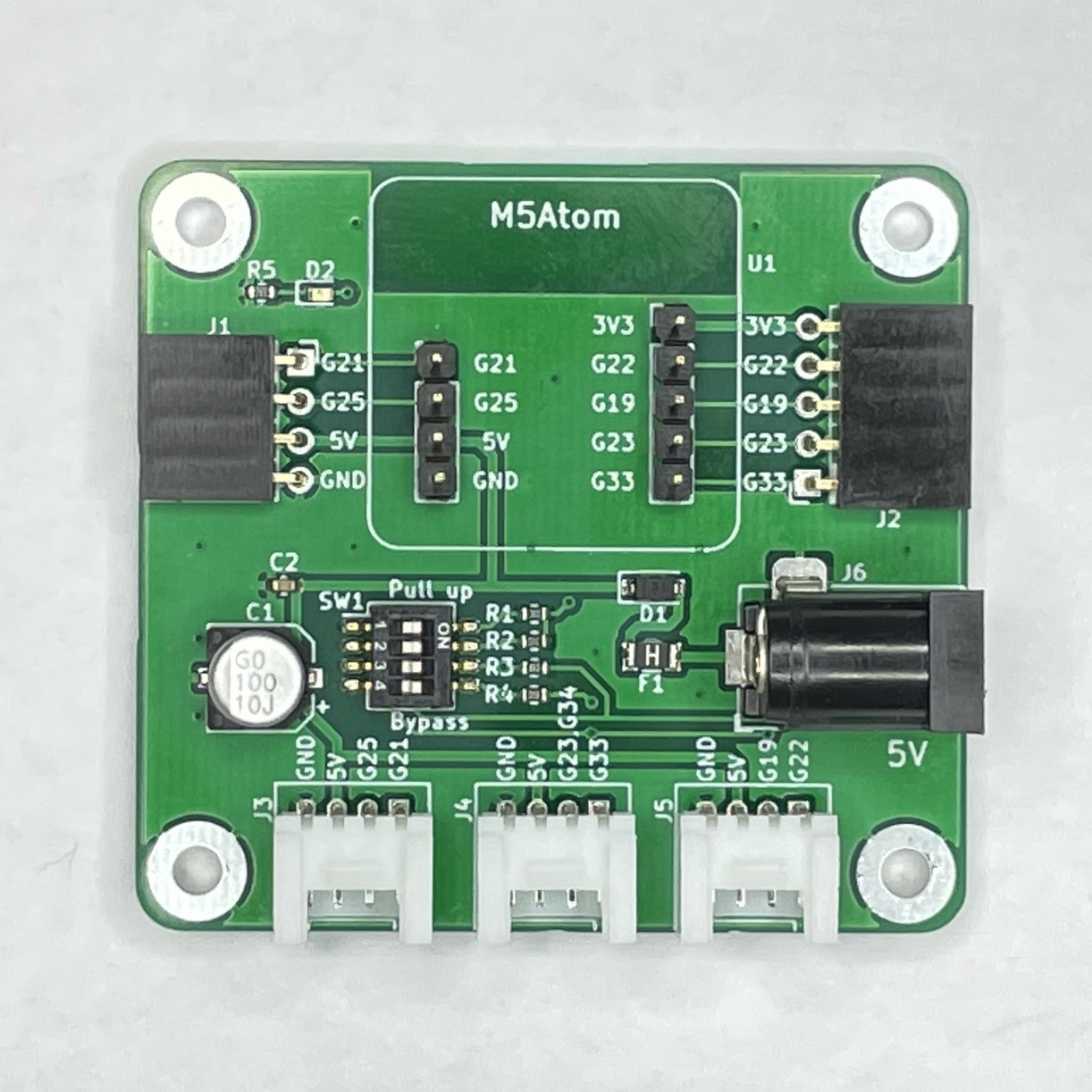
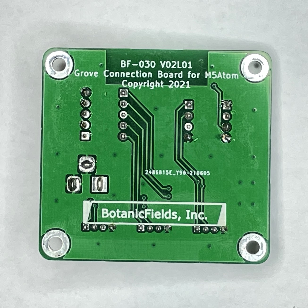
※ 動作中の電源の抜き差し (USB-C / DC ジャック) は、動作継続を保証できません。
「ENV ユニット」(I2C)、「M5 用光センサ・押しボタン 5 基板」(アナログ)、「DFPlayer-Mini用 Grove 接続基板」(UART) を同時接続し、USB-C または DC 5V 電源を接続しています。動作に使用したプログラム BF-030.ino は、温度・湿度・気圧・周囲の明るさをシリアルモニタに定期的に表示する一方、押しボタンで楽曲の演奏を制御(次の曲、前の曲、音量増、音量減、USB/microSD 切替)できます。
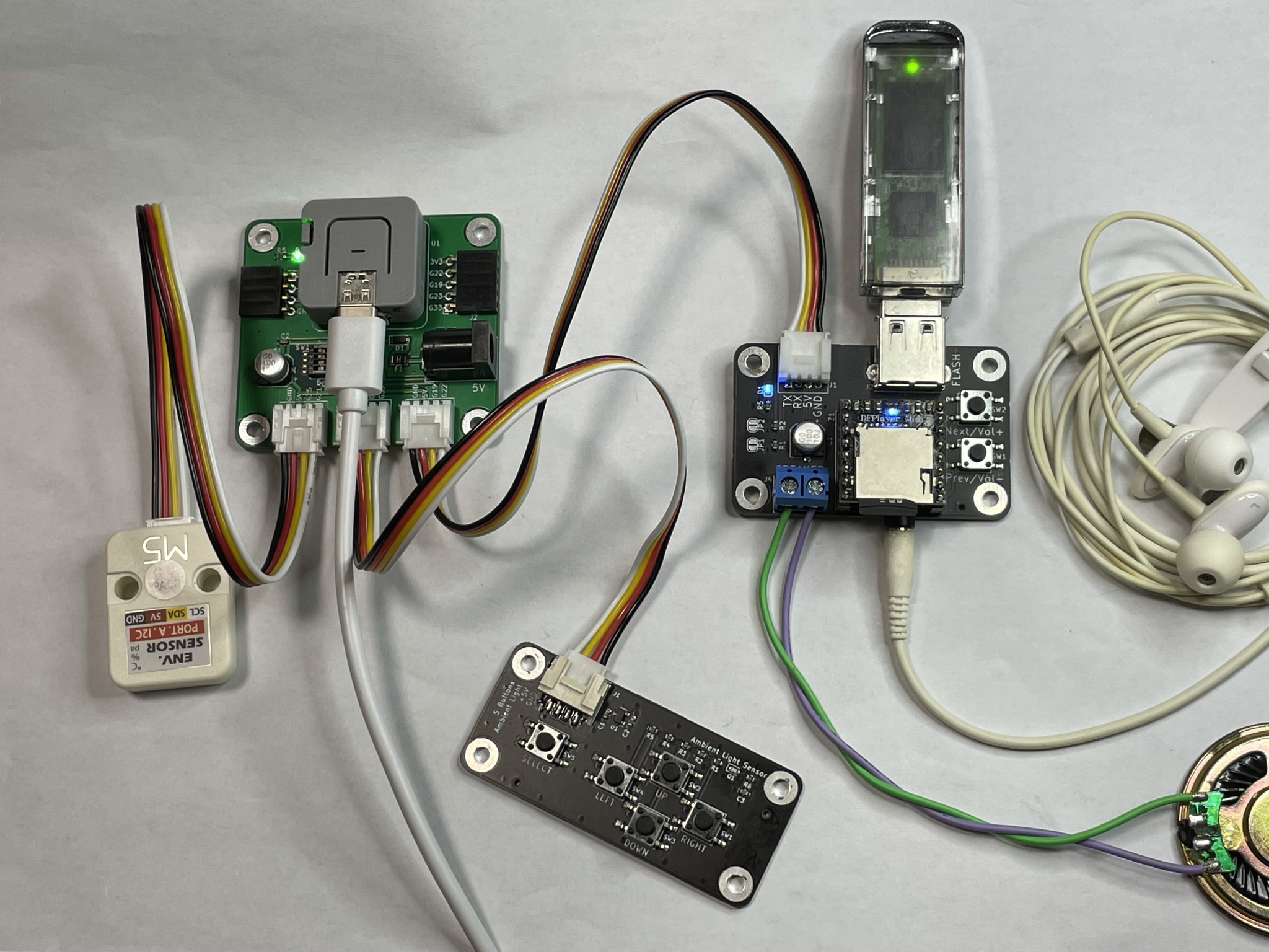
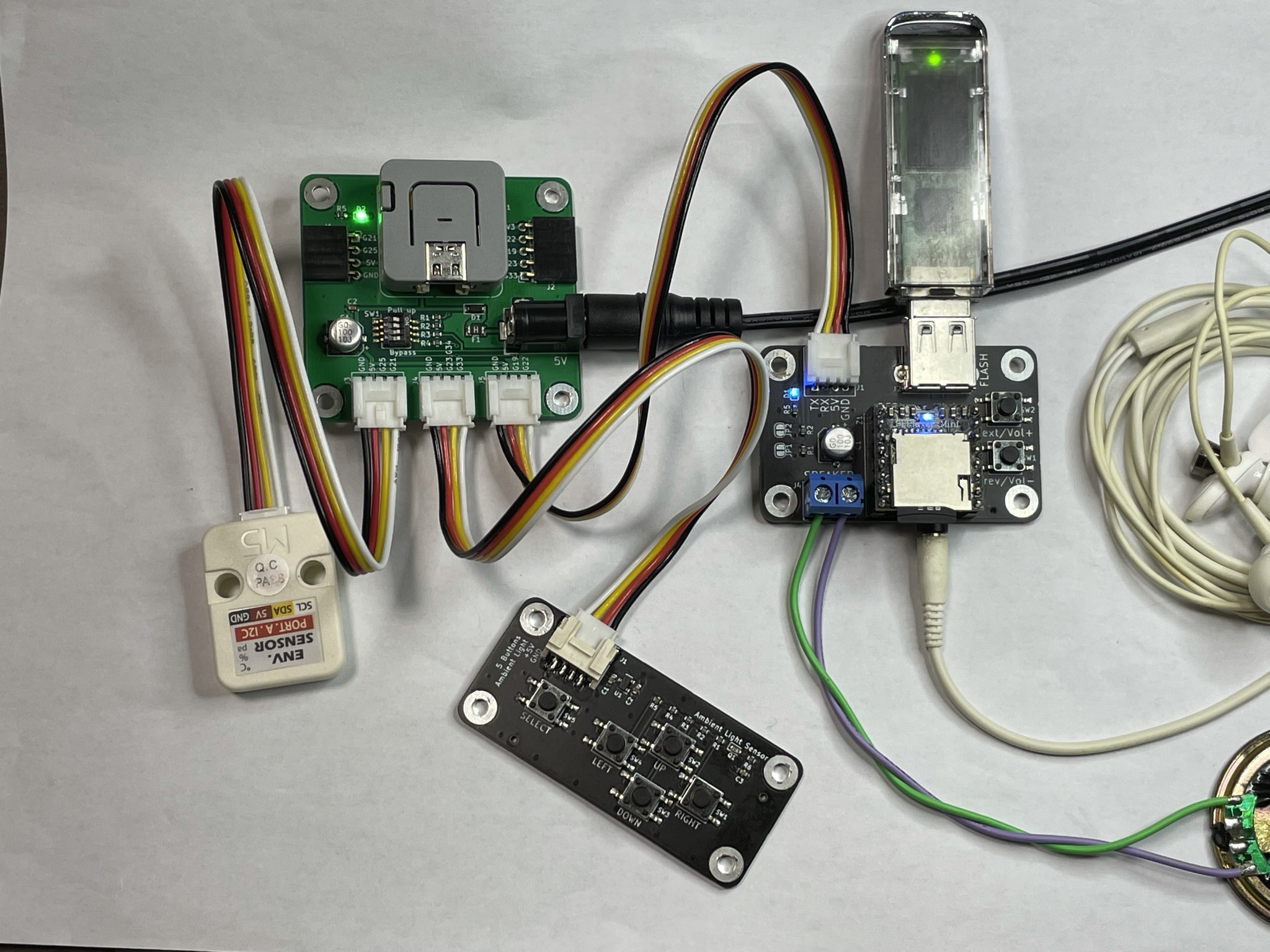
回路図をご確認ください。
| GROVE | pin 1 | pin 2 | pin 3 | pin 4 | 想定用途 | 備考 |
|---|---|---|---|---|---|---|
| J3 | G21 (SCL) | G25 (SDA) | +5V | GND | I2C | プルアップ抵抗(*1)設定可 |
| J4 | G33 | G23, G34 | +5V | GND | アナログ入力 | - |
| J5 | G22 (RX) | G19 (TX) | +5V | GND | シリアル | 保護抵抗(*2)バイパス可 |
(*1) DIP スイッチ 1, 2 を ON にすると、プルアップ抵抗 (10kΩ) が有効となります。I2C では M5Atom 内蔵のプルアップ機能があり、またデバイス側にもプルアップ抵抗があったりするため通常は不要ですが、外付けが必要な場合に使えます。
(*2) DIP スイッチ 3, 4 を ON にすると、保護抵抗 (1kΩ) をバイパスします。保護抵抗は、5V 系のシリアルインタフェースを 3.3V 系である M5Atom の RX に接続する場合の過電圧から保護します。3.3V 系との接続では保護抵抗をバイパスできます。3.3V で出力する TX には保護抵抗は不要と考えられますが、実験での接続ミスなどを考慮して使用することもできます。
| DIP スイッチ 番号 | 影響するピン | ON の場合 |
|---|---|---|
| 1 | G21 (SCL) | プルアップ抵抗 (10kΩ) を接続 |
| 2 | G25 (SDA) | プルアップ抵抗 (10kΩ) を接続 |
| 3 | G22 (RX) | 保護抵抗(1kΩ) をバイパス |
| 4 | G19 (TX) | 保護抵抗(1kΩ) をバイパス |
DC ジャックからの電源にはフューズ (PTC リセッタブル、保持電流 1.1A, トリップ電流 2.2A) があります。ちなみに M5Atom 内部には 5V 出力に 0.5A のフューズがあります。
| Qty | Value | Footprint | References |
|---|---|---|---|
| 2 | , | ||
| 2 | 10k | bf:BF@R_0603_1608Metric | R1, R2 |
| 2 | 1k | bf:BF@R_0603_1608Metric | R3, R4 |
| 1 | 100n | bf:BF@C_0603_1608Metric | C2 |
| 1 | 100u | bf:BF@CP_Elec_6.3x5.3 | C1 |
| 1 | 1A | bf:BF@Fuse_1206_3216Metric | F1 |
| 1 | 3.3k | bf:BF@R_0603_1608Metric | R5 |
| 1 | ADC | OPL_Connector:HW4-2.0-90D | J4 |
| 1 | B5819W | bf:BF@D_SOD-123 | D1 |
| 1 | Barrel_Jack_Switch | bf:BF@BarrelJack_Horizontal | J6 |
| 1 | I2C | OPL_Connector:HW4-2.0-90D | J3 |
| 1 | LED | bf:BF@LED_0603_1608Metric | D2 |
| 1 | LOGO | bf:BF@logo5 | G*** |
| 1 | M5Atom | bf:BF@M5Atom | U1 |
| 1 | M5Atom-1 | Connector_PinSocket_2.54mm:PinSocket_1x04_P2.54mm_Horizontal | J1 |
| 1 | M5Atom-2 | Connector_PinSocket_2.54mm:PinSocket_1x05_P2.54mm_Horizontal | J2 |
| 1 | PU-BYP | Button_Switch_SMD:SW_DIP_SPSTx04_Slide_KingTek_DSHP04TS_W7.62mm_P1.27mm | SW1 |
| 1 | RXTX | OPL_Connector:HW4-2.0-90D | J5 |
The 21 most common of 25 parts.
It measures 54 × 50 mm and has 2 copper layers, 1.6 mm thick.
25 parts, built around the B5819W. The full list of its parts is on this page, with links to each part's symbol and footprint where PCBKit's library has them.
From the botanicfields/PCB-Grove-for-M5Atom repository on GitHub, at the commit this page was made from: the board is PCBV02L01/KiCad/bf-030.kicad_pcb. PCBKit opens the board in the browser, with nothing to install.
Its repository publishes it under the CC0-1.0 licence: you may reuse it on that licence's terms (keep the author's notice, and for a copyleft licence share your changes alike).

pms67/LittleBrain-STM32F4-Sensorboard
STM32F4-based PCB interfacing with a variety of sensors.

TobleMiner/DC-UPS
A small DC UPS, designed to keep small appliances like consumer network equipment running during power outages

joeltroughton/uSMU
Credit card-sized, USB-powered 4 quadrant source-measure unit hardware and firmware

DerSpatz/PCB-reflow-solder-heat-plate
hardware design for a PCB reflow solder heat plate

megamind4089/STeMCell
STM32F4 breakout board in pro micro pinout. Designed mainly for ergo split keyboards.

rusefi/hw_microRusEfi
microRusEfi board for rusEfi ECU

TobleMiner/ESP32-Devkit-Type-C
Breadboard friendly, USB Type C enabled, ESP32 Devkit compatible, JLCPCB assembly ready ESP32 devboard