
2 layers52.1 × 25.3 mm
Barrel roll
bobis1/barrel-roll
Currently there are some issues with this project ## TODO - Fix the pcb to have the correct footprint
12 parts

 bobis1/barrel-roll
Currently there are some issues with this project ## TODO - Fix the pcb to have the correct footprint
Barrel roll is an open-source printed circuit board by bobis1, from the bobis1/barrel-roll repository on GitHub. It is a 2-layer board of 46.7 × 53 mm with 15 parts on 25 nets, routed with 146 tracks and 6 vias.
It is built around the DRV8833PW. It belongs with the RP2040 boards of this library.
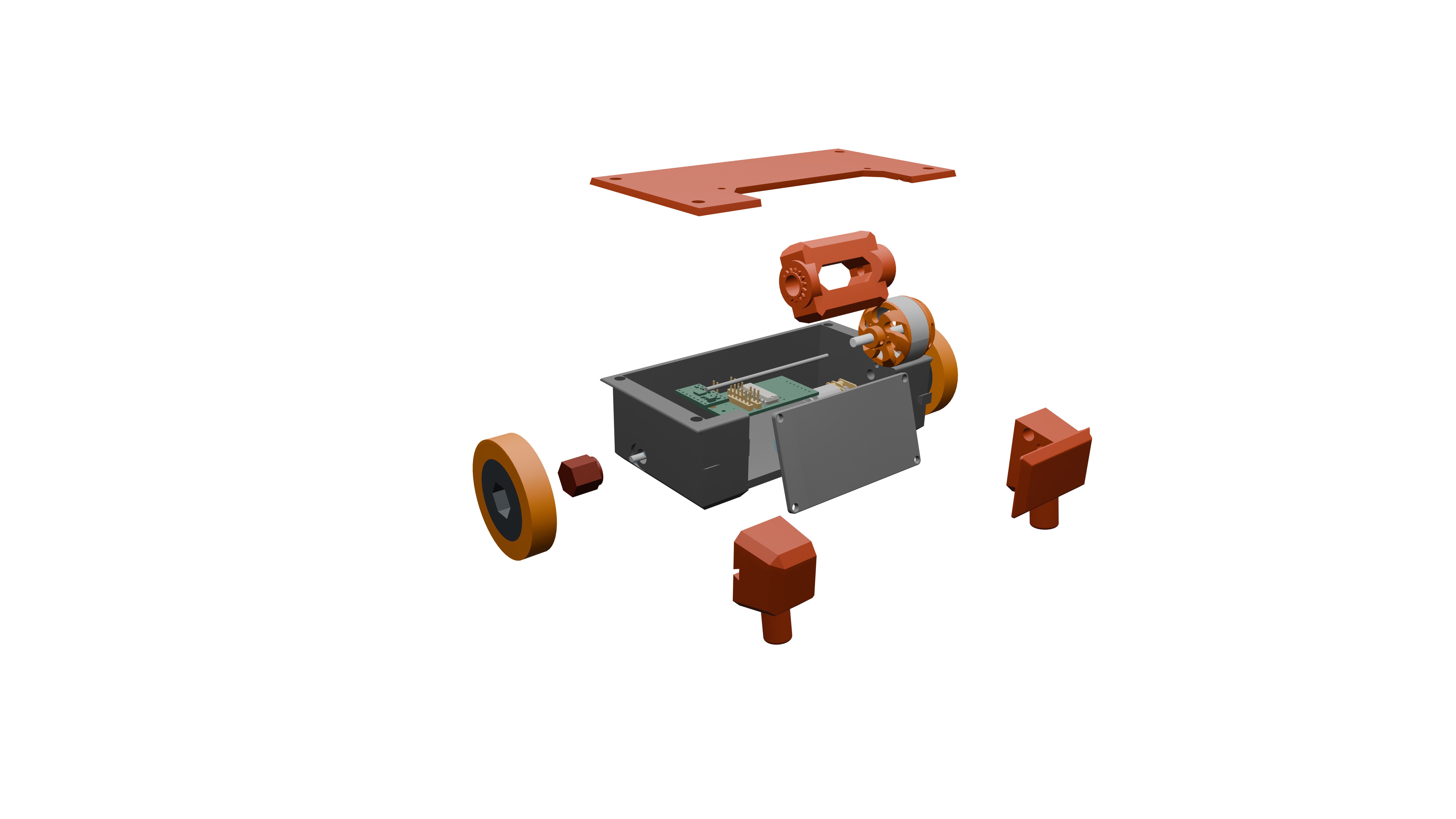 Slightly dissassembled view of barrel roll.
Currently there are some issues with this project
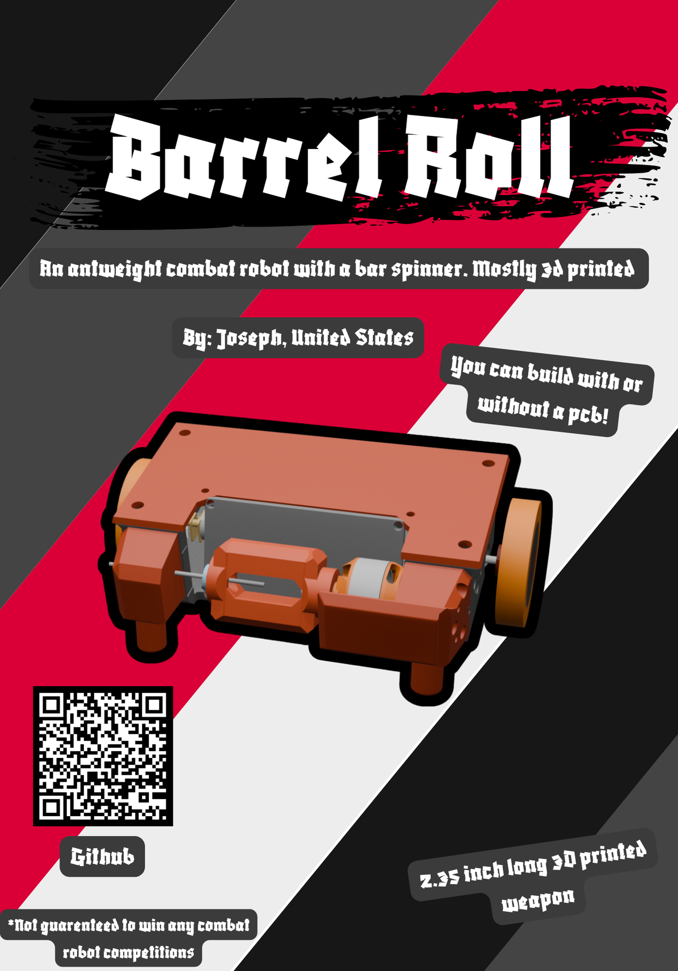
Barrel roll is a 150g combat robot that has a 2.706693 inch long bar spinner. There are two options for the microcontroller of the robot. Right now I have a pcb designed with a RP2040 in mind. I also have a version of the schematic/firmware with an esp32 as the microcontroller.
I created barrel roll because the way I got into robotics/programming/stem in general is through watching various battlebots-like shows and videos on the internet. So for a long time, I wanted to create my own battle bot. Once I saw the Fallout event by Hack Club I decided that it would be an amazing opportunity to create something similar to what got me into this in the first place. My goal with barrel roll is to create a bar spinner battle bot that could compete in the 150g weight class.(not necessarily well)
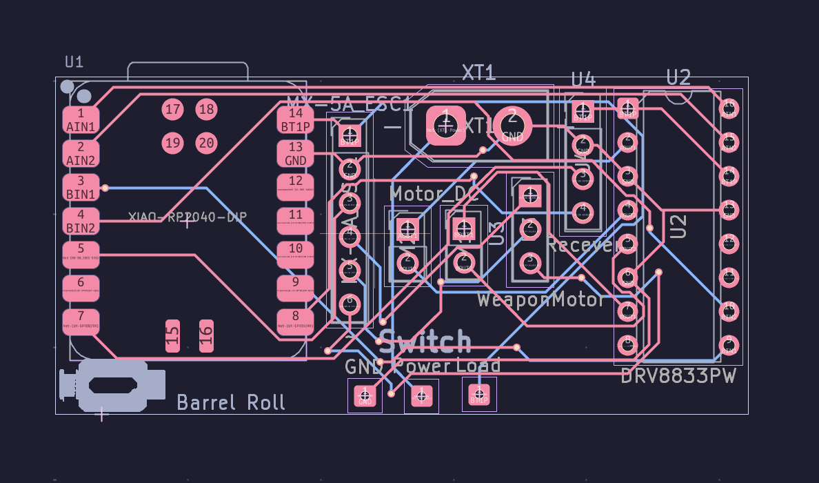
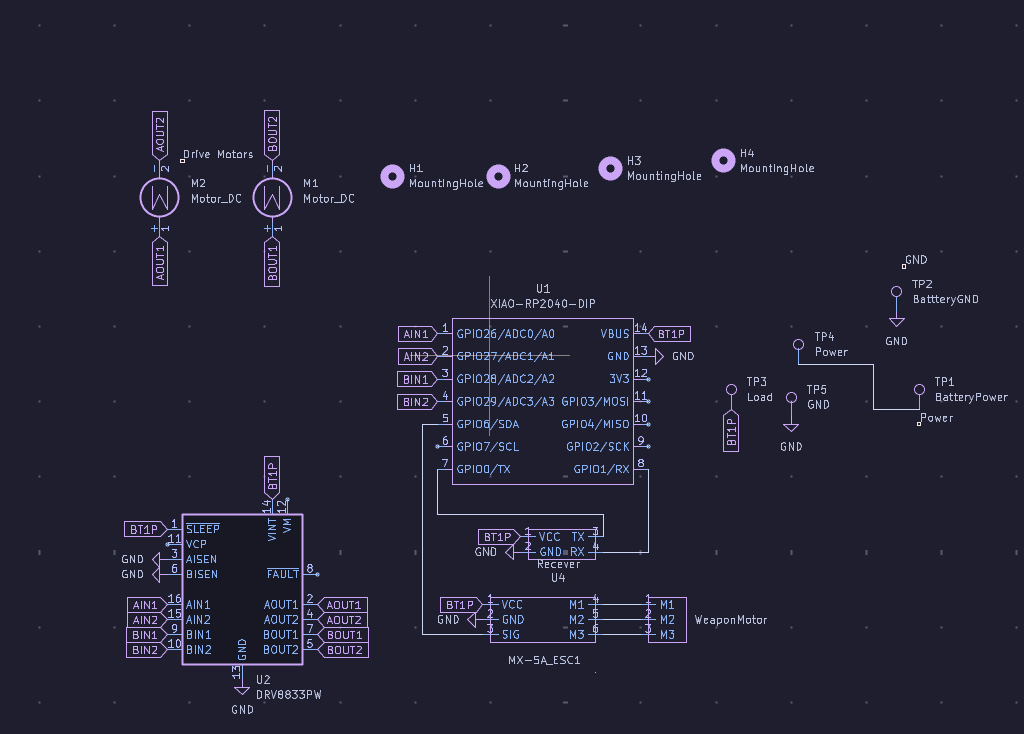 Above are the images of the PCB version of the electrical components of the robot(To be honest right now it feels more like a glorified pinout board)
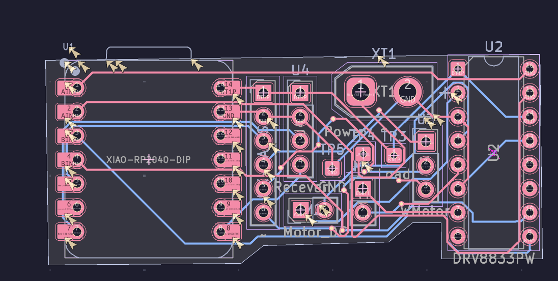 Above is a picture of the pcb using DIP sodering. The schematic is the same as the original SMD sodered PCB.
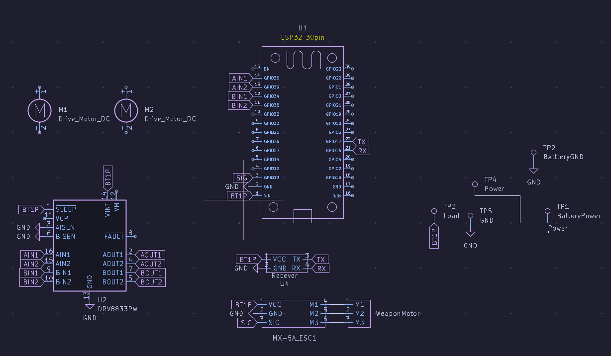 The above is a picture of the schematic for anyone using the DOIT esp32 devkit v1. I made this one because it could cut down on the cost of the project as a whole.
Onshape link: https://cad.onshape.com/documents/4d0cf8c11fd66439fc3e30b0/w/a8064dfad10d7d33689fe150/e/62081654516d84e6ca0ee160
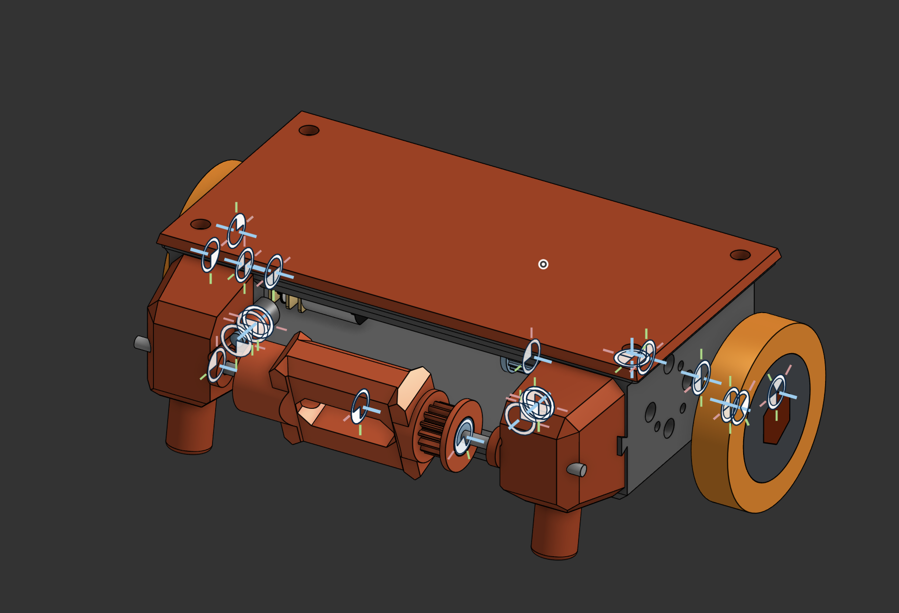 A note about the assembly: I could not find 3d models of the bearings I wanted to use so I made a model with the same dimensions as the bearings. /n
As a note I intend on using the PCB SMD BOM.
For this project I made several usable versions of the electronics. I did this to make sure that when it comes time for me to actually build this I can still build it even if I don't have some of the equipment that I need. The main distinction between all of the options are the different ways to soder on the microcontroller. For the no pcb method you could just use an esp32 instead of a xiao rp2040.
IF you are using a PCB to create Barrel Roll then you need to get the Gerbers.zip from barrel-roll folder in the repo. After this you need to go to your preferred PCB manufacteror of your choice to have it manufactured. Gerbers.zip You could use this as a reference for SMD sodering the xiao RP2040.
If you are using the DIP version of the pcb then you need to follow many of the same steps as using the SMD pcb method. However, since you are using DIP for the RP2040, sodering the PCB should be significantly simpler. Gerbers.zip
If you are not using a PCB your costs will be a little bit lower since you don't need to by the PCB. To find the wiring diagram you can look in the barrel-roll-nopcb folder of the repo. This is a kicad project that contains a wiring diagram if you have a DOIT ESP32 devkit 1(The esp32 from the electronics kits that commonly come from hackclub events).
In order to assemble the weapon system properly you want to make sure that you place the parts on the axle in the correct order. Axle stopper, Weapon with bearing, Axle stopper. Then you need to place the axle onto the two pieces on the Side shell.
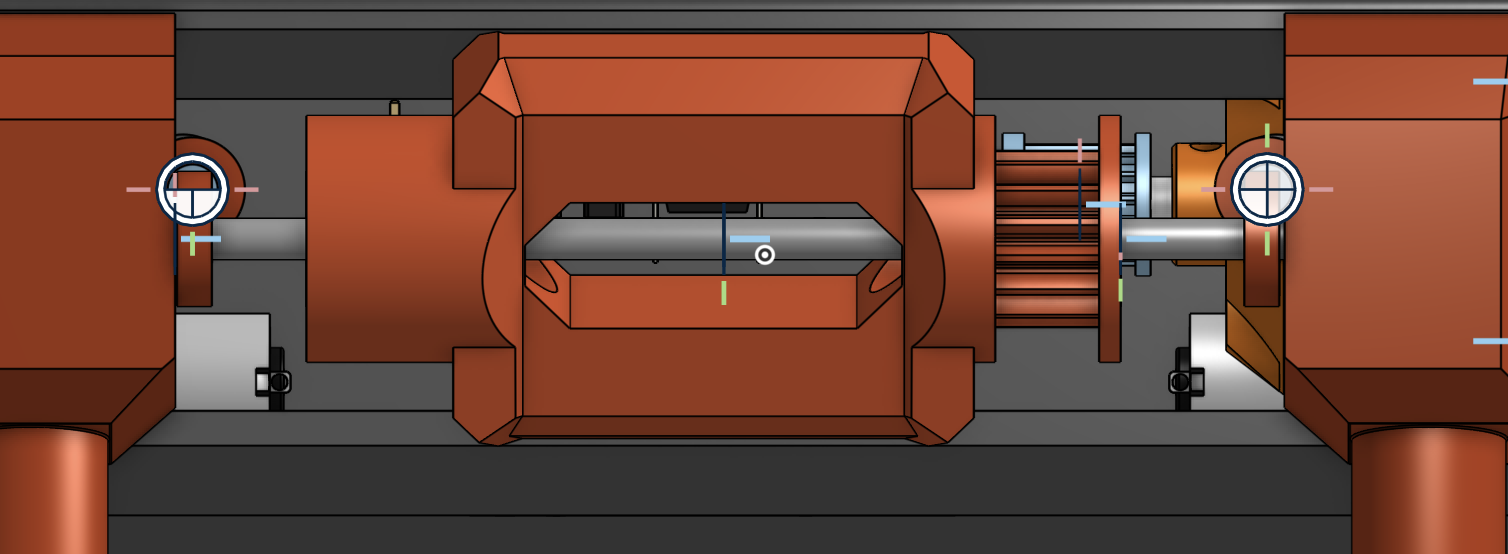 Here is a picture of the front assembly that you should try to replicate.
To assemble the barrel-roll you first need to print out the parts specified in the onshape document. All the parts in the FINAL folder must be printed There will be a note with the quantity and the infill amount. The fillament for all of these will be up to you. I will personally be using TPU. If you do not want to go into the Onshape, All of the final .step files will be in models/FinalParts.\
You need to print:
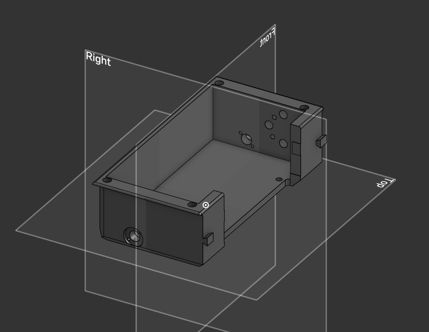 .Step File
The above is the main shell
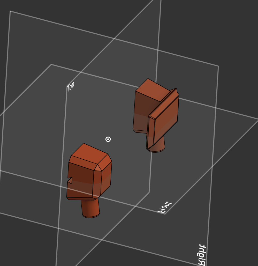 .Step File
The above is the side shell For the rest of it you should look at the onshape document.
To assemble the Main shell with the Side Shells you can use the bowtie connector along side the fastening rod to attach each part of the SIDE_SHELL without the use of metal connectors. To do this, follow the instructions below.
Assemblint the weapon system involves, using the weapon motor screws to secure the motor to the side of the shell with the "shield" like so 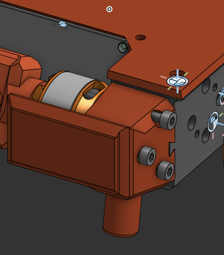 . Next to finish securing the weapon onto the motor, simply slide the weapon onto the motor shaft then place the cap onto the motor shaft like so
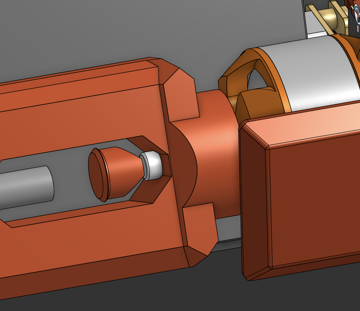 .
With this you are almost done with the weapon motor system. n/
The next thing that you need to do is slide the shaft into the bearings. Before doing this you need to cut the (90mm) shaft into a 60mm shaft.(The reason for this is to cut down on the weight and to to make the shaft super long.) An alternative to this would be to print out a similarly sized rod out of ABS or petg Here
For the electronics you want to reference the Schematic and the 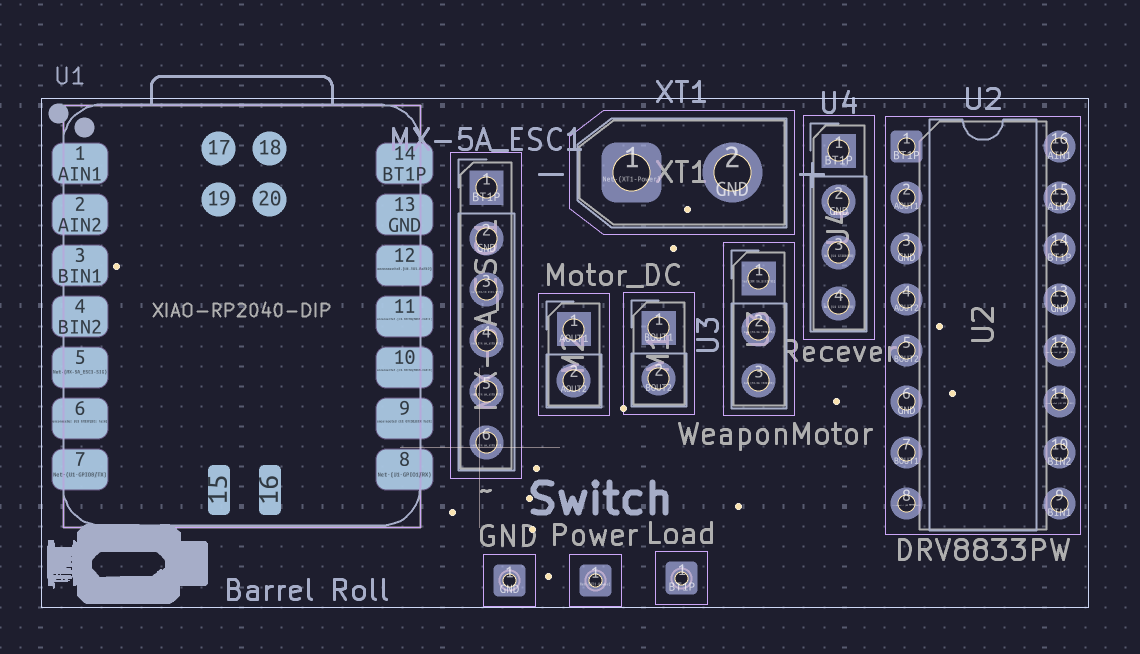 . First you want to wire the drive motors to AOUT and BOUT pin holes respectively. Do this for both of the drive motors. The next thing that you want to do is attach the motor driver to the respective pins. Next you have to attach the ESC motor controller for the brushless motor. Next you have to soder the jumper wires to their respective ports based on the schematic of the pcb. The schematic should have all the pins that you need to soder to.
To use barrel roll you need to connect the radio recever to the radio sender. After this you should be able to control the robot using your controller.
There are three BOMs one for SMD, DIP and one if you are simply using a esp32. The "master" BOM can be found here BOM(This will be the most convienient to use and will be the most updated in the coming months.)
| Qty | Value | Footprint | References |
|---|---|---|---|
| 4 | MountingHole | MountingHole:MountingHole_2.5mm | H1, H2, H3, H4 |
| 2 | Motor_DC | Connector_PinHeader_2.54mm:PinHeader_1x02_P2.54mm_Vertical | M1, M2 |
| 1 | DRV8833PW | Package_DIP:DIP-16_W7.62mm | U2 |
| 1 | GND | Connector_Wire:SolderWire-0.1sqmm_1x01_D0.4mm_OD1mm | TP5 |
| 1 | Load | Connector_Wire:SolderWire-0.1sqmm_1x01_D0.4mm_OD1mm | TP3 |
| 1 | Power | Connector_Wire:SolderWire-0.1sqmm_1x01_D0.4mm_OD1mm | TP4 |
| 1 | Recever | Connector_PinHeader_2.54mm:PinHeader_1x04_P2.54mm_Vertical | U4 |
| 1 | WeaponMotor | Connector_PinHeader_2.54mm:PinHeader_1x03_P2.54mm_Vertical | U3 |
| 1 | XIAO-RP2040-DIP | Seeed Studio XIAO Series Library:XIAO-RP2040-DIP | U1 |
| 1 | ~ | Connector_PinHeader_2.54mm:PinHeader_1x06_P2.54mm_Vertical | MX-5A_ESC1 |
| 1 | ~ | Connector_AMASS:AMASS_XT30UPB-F_1x02_P5.0mm_Vertical | XT1 |
bobis1/barrel-roll
Currently there are some issues with this project ## TODO - Fix the pcb to have the correct footprint

bobis1/barrel-roll
Currently there are some issues with this project ## TODO - Fix the pcb to have the correct footprint


RoboticsBrno/Robutek
Robůtek je robotická platforma založená na čipu ESP32-S3. Je velice rozšitiřelný, ale ze základu umí jezdit, kreslit fixou, jezdit po čáře, pohybovat se bludištěm. Programování je přes Jaculus.


CWRUbotix/Micromouse-2023-24
A fully autonomous maze-solving not-quite-mouse-sized robot.

FIPATECH/CDFR26_PAMI
Open source firmware and PCB for a differential mobile robot (PAMI) based on ESP32-S3 - Coupe de France de Robotique

empriselab/mote
A low cost, high confidence mobile robot optimized for education.

interspecifics/ComunicacionesEspeculativas
Es un proyecto basado en una máquina que es capaz de observar y aprender de microorganismos para crear un score audiovisual a partir de los patrones que encuentre en su comportamiento.

nochkin/esp-line-follower
A simple educational project to build a line following 2WD robot
It measures 46.7 × 53 mm and has 2 copper layers, 1.6 mm thick.
15 parts, built around the DRV8833PW. The full list of its parts is on this page, with links to each part's symbol and footprint where PCBKit's library has them.
From the bobis1/barrel-roll repository on GitHub, at the commit this page was made from: the board is Electronics/barrel-roll-pcb/backups/barrel-roll.kicad_pcb and its schematic Electronics/barrel-roll-DIPPCB/barrel-roll-DIPPCB_pro.kicad_sch. PCBKit opens the board in the browser, with nothing to install.
Its repository states no licence, so its author keeps all rights: ask bobis1 before reusing the design.