
4 layers102.9 × 96.7 mm
PicoGUS chipdown
polpo/picogus
Emulation of ISA sound cards and CD-ROM on Raspberry Pi Pico (GUS, SB/Adlib, MPU-401, Tandy, CMS, Panasonic CD-ROM) with USB mouse/joystick support
99 parts805

 bobis1/learnboard
A custom midi keyboard
Learnboard is an open-source printed circuit board by bobis1, from the bobis1/learnboard repository on GitHub. It is a 2-layer board of 281.4 × 126 mm with 57 parts on 70 nets, routed with 981 tracks and 81 vias.
It is built around the PCM5100PW. Its parts include 26 diodes, 17 switches, 10 resistors and 1 IC. It belongs with the RP2040 boards of this library.
Learnboard is a midi keyboard that I designed to "get my foot through the door" of creating hardware projects. This keyboard has 8 keys(16 physical switches). This keyboard has the feature to load "songs" into it. This keyboard also has LEDs that are under each of the 8 keys. These will light up whenyou hit the key or if the song that is loaded requires it.
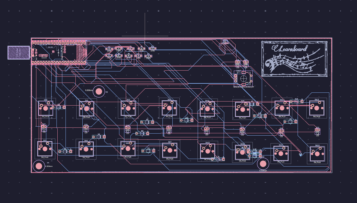
The learnboard's PCB has 2 layers.
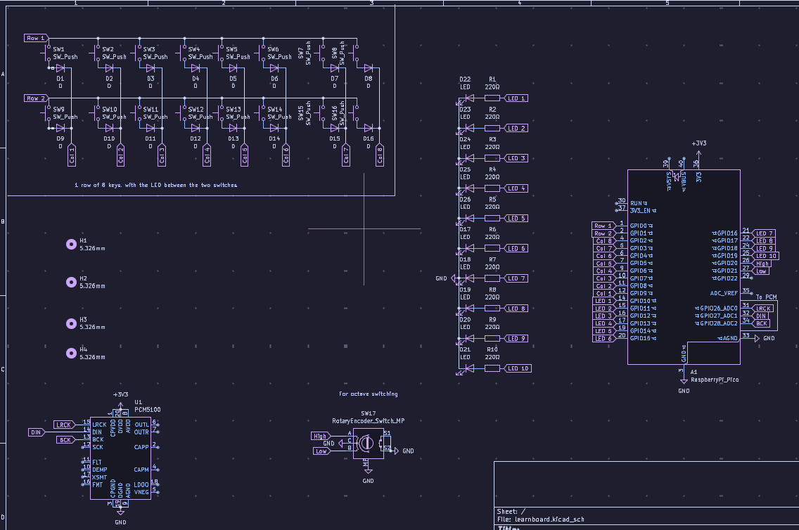
Here is the schematic for the PCB
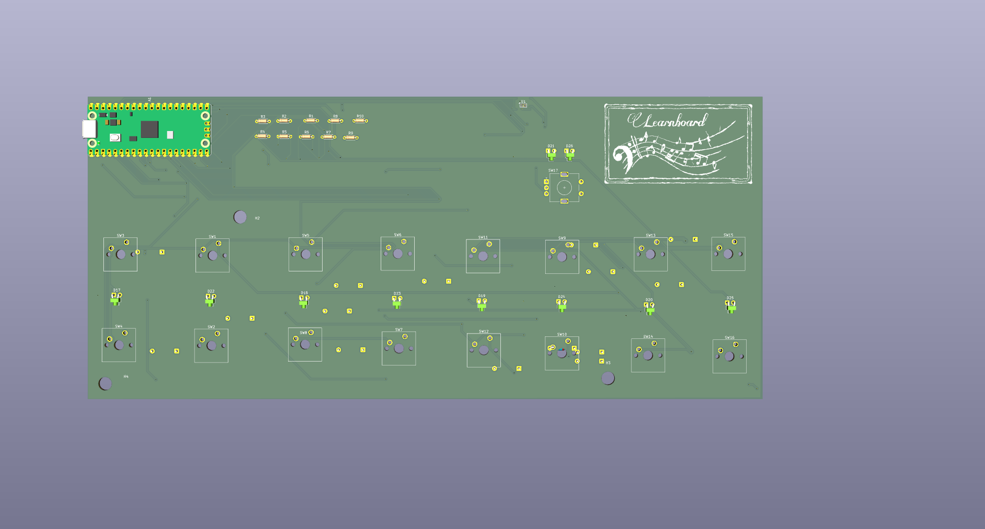
Here is a 3D model of the pcb
To use the learnboard in the most basic context you simply hit the keys and the corresponding LED on that key will light up. To use the non freeplay mode you must use the webui that is inside the respective folder(This is a html document). From there you can adjust many things with the learnboard(Such as volume). The song loading works by loading .json files through the webui. To connect the midi keyboard to the webui you have to connect the midi keyboard to your computer. Then click the connect button on the connect window(These windows are partially based on the webos jam).
You can get the firmwware from the firmware folder of the repo. For this you can follow the circuit python tutorial for the board here: https://circuitpython.org/board/raspberry_pi_pico/ .
(When I actually have everything I will have images)
To assemble the learnboard you must first 3d print the case along with it's connectors. You need to print both parts of Case.step and caseTop.step. You need to print 2 Connector.step parts and 2 ConnectorWedge.step parts(This is if you are using printed connectors to connect the top and bottom of the case). You need 4 prints of teh PrintConnector.step file. When you have these printed slot the PrintConnectors into their respective bowtie slots in the cases.
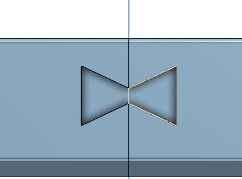 (Looks like this). If you are using the printed connectors slot the Connector.step results into the two holes on the cases.Then put the wedge up the fork of the connector.
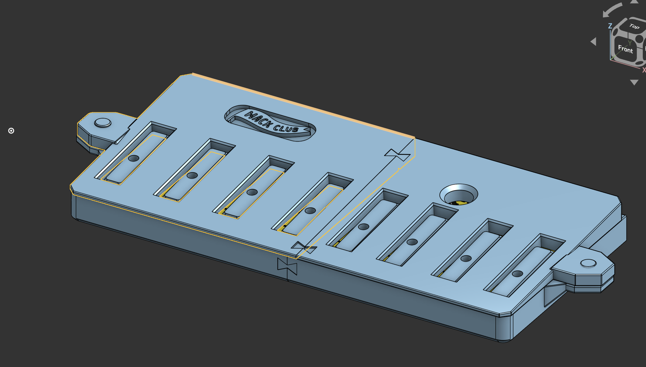 The case can be printed in several pieces. To hold the case pieces that are printed seperately there are "bowtie" connectors to connect these. The connector for the case top and the case bottom can be printed however a machine screw can also be used for that purpose. The .step files will be in the CAD folder. When printing I split the case into four parts. Two of the parts are in the Case.step file and the other two are in the caseTop.step file
Here is the link to the onshape.
https://cad.onshape.com/documents/c06ae8a09bf7d6a8ae56adf7/w/ad5690a7cddb318995ea60e9/e/03d033c41fe9f6e94a9a3737
Here is the BOM. I put n/a in place of anything that I already had.
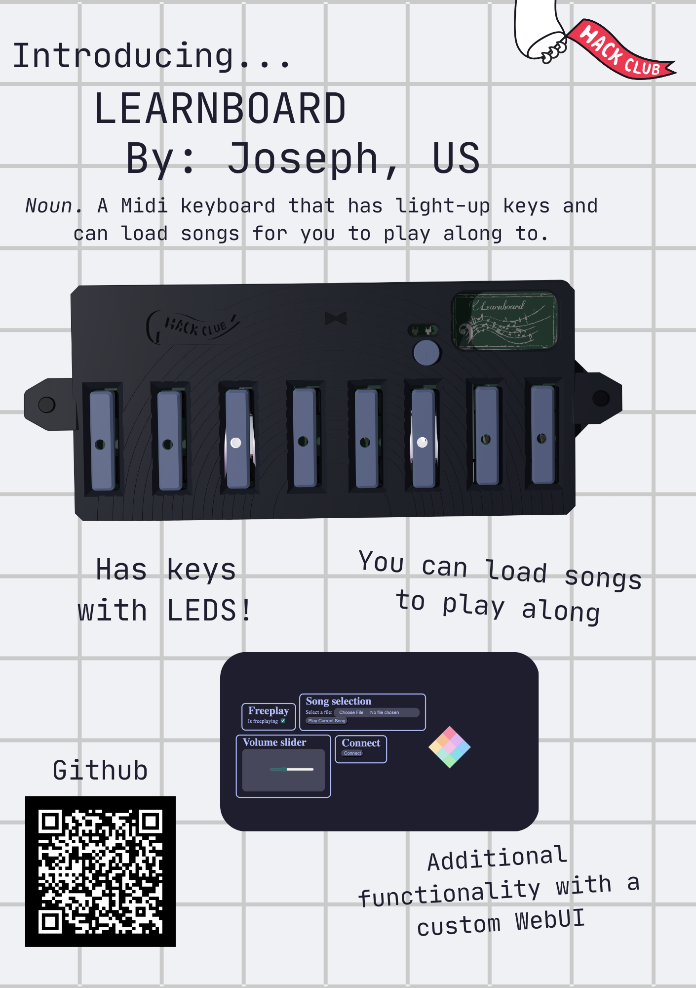 The .pdf file for the poster can be found here
https://blueprint.hackclub.com/starter-projects/midi This is a project I got alot of the idea from. https://jams.hackclub.com/batch/webOS Where I got the ideas for the windows from
| Qty | Value | Footprint | References |
|---|---|---|---|
| 16 | SW_Push | Button_Switch_Keyboard:SW_Cherry_MX_1.00u_PCB | SW1, SW2, SW3, SW4, SW5, SW6, SW7, SW8, SW9, SW10, SW11, SW12, SW13, SW14, SW15, SW16 |
| 15 | D | Diode_THT:D_T-1_P10.16mm_Horizontal | D1, D2, D3, D4, D5, D6, D7, D8, D9, D10, D11, D12, D13, D14, D15 |
| 10 | 220Ω | Resistor_THT:R_Axial_DIN0204_L3.6mm_D1.6mm_P5.08mm_Horizontal | R1, R2, R3, R4, R5, R6, R7, R8, R9, R10 |
| 10 | LED | LED_THT:LED_D1.8mm_W1.8mm_H2.4mm_Horizontal_O1.27mm_Z1.6mm | D17, D18, D19, D20, D21, D22, D23, D24, D25, D26 |
| 2 | 5.326mm | MountingHole:MountingHole_5.5mm | H2, H4 |
| 1 | D | Diode_SMD:D_0201_0603Metric | D16 |
| 1 | PCM5100 | PCM5100APWR:SOP65P640X120-20N | U1 |
| 1 | RaspberryPi_Pico | Module:RaspberryPi_Pico_Common_Unspecified | A1 |
| 1 | RotaryEncoder_Switch_MP | Rotary_Encoder:RotaryEncoder_Alps_EC11E-Switch_Vertical_H20mm | SW17 |
It measures 281.4 × 126 mm and has 2 copper layers, 1.6 mm thick.
57 parts, built around the PCM5100PW. The full list of its parts is on this page, with links to each part's symbol and footprint where PCBKit's library has them.
From the bobis1/learnboard repository on GitHub, at the commit this page was made from: the board is PCB/learnboard.kicad_pcb and its schematic PCB/learnboard.kicad_sch. PCBKit opens the board in the browser, with nothing to install.
Its repository states no licence, so its author keeps all rights: ask bobis1 before reusing the design.
polpo/picogus
Emulation of ISA sound cards and CD-ROM on Raspberry Pi Pico (GUS, SB/Adlib, MPU-401, Tandy, CMS, Panasonic CD-ROM) with USB mouse/joystick support


intergalaktik/Extension_Boards_for_Olimex_GateMate
Simple extension boards for Olimex GateMate FPGA Board

saybur/dac-attack
S/PDIF to line-level audio board for use with retro computer device emulators, such as ZuluSCSI and friends.


mbeayou/esp32-hifi-bluetooth-speaker-pcb-board
A custom high-fidelity Bluetooth speaker PCB featuring the ESP32 (I2S), PCM5100 DAC, and TPA3116D2 Class D Amplifier. Includes Schematics, Gerber files, and BOM.

sparkfun/SparkFun_Qwiic_WAV_Trigger_Pro
An STM based WAV/MIDI device with a full speed USB interface.
