4 layers90 × 70 mm
InclinationMeter
soldernerd/InclinationMeter
A battery-powered, Bluetooth-enabled precision electronic level instrument for machine tool geometry inspection and granite surface plate qualification.
118 parts

 saybur/dac-attack5
S/PDIF to line-level audio board for use with retro computer device emulators, such as ZuluSCSI and friends.
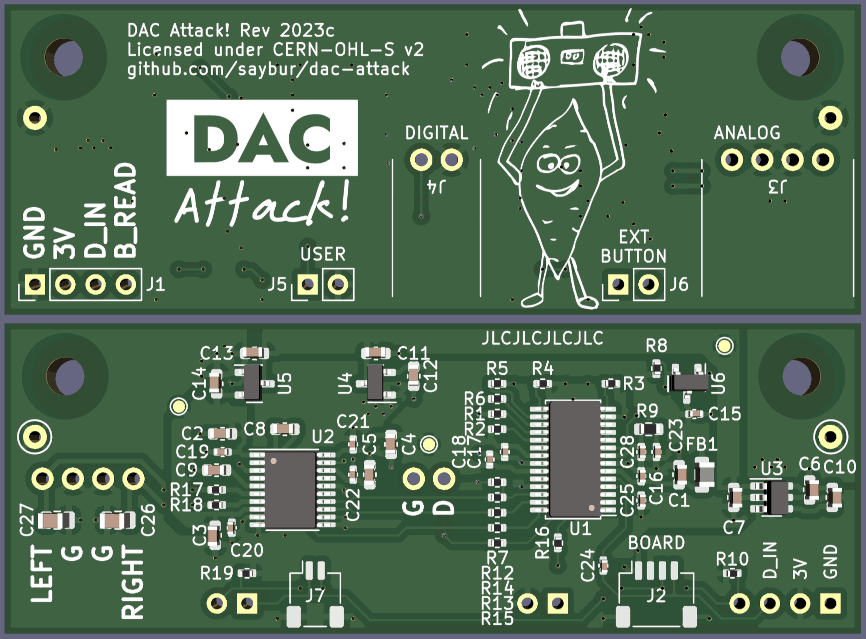
Dac attack is an open-source printed circuit board by saybur, from the saybur/dac-attack repository on GitHub, published under the CERN-OHL-S-2.0 licence. It is a 2-layer board of 71.8 × 26 mm with 69 parts on 43 nets, routed with 434 tracks and 84 vias.
It is built around the SD6210A, XC6206P332MR and PCM5100PW, with the GZ2012D601TF among its other parts. Its parts include 28 capacitors, 18 resistors, 7 connectors and 6 ICs. It belongs with the audio and music boards of this library.


A small S/PDIF to line-level audio adapter design. The intended use case is with some versions of ZuluSCSI, though the design should work with any S/PDIF compatible output source generating a TTL-compatible signal.
Used with a compatible board, and the appropriate firmware, this allows sending audio to a retro computer. See later sections for usage information.
As of this writing, only some ZuluSCSI variants offer audio output. This list may change in the future. Refer to the ZuluSCSI project page for details about audio output support.
This project is made available under the CERN Open Hardware Licence strongly-reciprocal variant version 2, available at LICENSE.
This source is distributed WITHOUT ANY EXPRESS OR IMPLIED WARRANTY, INCLUDING OF MERCHANTABILITY, SATISFACTORY QUALITY AND FITNESS FOR A PARTICULAR PURPOSE. Please see the CERN-OHL-S v2 for applicable conditions.
ZuluSCSI™ is a registered trademark of Rabbit Hole Computing™, used with permission.
The author has had JLCPCB assemble these boards as prototypes. The files
dac-attack-bom.csv and dac-attack-top-pos.csv files were used successfully,
though caution should still be excercised: other open-source hardware projects
have reported some inconsistency in individual orders using files like these.
Adding through-hole components to assembled boards is relatively straightforward. The choice of what connectors to solder is up to the user:
Part numbers for through-hole parts are in bom-full.csv.
The screw holes on the board are spaced to match a 2.5" hard drive, which is the same pattern on most ZuluSCSI boards. Use standoffs to prevent shorting connections. An example mount is shown below. The full BOM has some options, which you can probably also find at your local hardware store or a convenient online retailer.
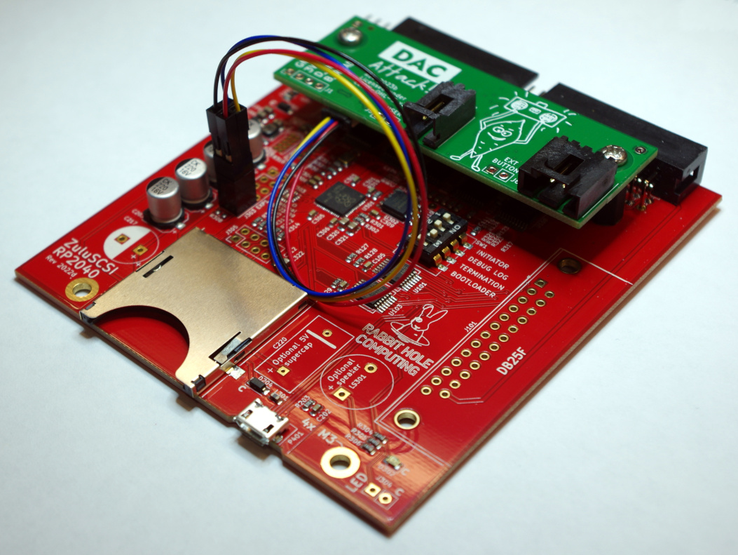
Most parent boards use either a 0.1" holes or a matching 4-pin modular connector. Instructions vary between these two board types.
Important note: DAC Attack uses a 4-pin connector that matches common hobbyist I2C formats; however, the board is not compatible with I2C.
Carefully solder a socket on the parent board. Most will need either a 2x2 or 1x4 connector for this. Example parts to order are in the BOM. You only need to solder to points labeled GND, 3V0, SCL, and SDA on the bottom of the board. Again, use great care during this process to avoid damaging anything.
Once soldered, connect a suitable cable from the socket to the DAC's modular connector. Potential options are listed in the BOM. If the DAC's modular connector is not populated, or you would prefer not to use it, the separate labeled points on the DAC may be used instead.
If using the modular cable pin breakout version, colors should correspond as follows:
If your parent board is equipped with a 1x4 modular connector, you're all set: just connect the board to the DAC.
If the parent board does not have a modular connector, the most straightforward option is to add the modular connector, likely part BM04B-SRSS-TB(LF)(SN).
Once you have installed the board and applied correct firmware (if needed), all that remains is connecting the 'analog' port to a suitable target. Most period- correct sound cards will use either a 3-pin or 4-pin cable for connecting a CD drive. This pinout is also compatible with the one used on retro Mac computers.
It is recommended to test your configuration to determine if stereo audio is being handled appropriately. If it is not, rotate the cable in the socket.
| Qty | Value | Footprint | References |
|---|---|---|---|
| 8 | 100nF | Capacitor_SMD:C_0402_1005Metric | C15, C16, C17, C18, C19, C20, C21, C22 |
| 8 | 47K | Resistor_SMD:R_0402_1005Metric | R1, R2, R3, R4, R5, R6, R7, R8 |
| 7 | 10uF | Capacitor_SMD:C_0603_1608Metric | C1, C2, C3, C4, C5, C6, C7 |
| 7 | 2.2uF | Capacitor_SMD:C_0603_1608Metric | C8, C9, C10, C11, C12, C13, C14 |
| 5 | 22 | Resistor_SMD:R_0402_1005Metric | R12, R13, R14, R15, R16 |
| 3 | 22nF | Capacitor_SMD:C_0402_1005Metric | C23, C24, C25 |
| 3 | 470 | Resistor_SMD:R_0402_1005Metric | R17, R18, R19 |
| 2 | 2.2nF | Capacitor_SMD:C_0805_2012Metric | C26, C27 |
| 2 | GND | TestPoint:TestPoint_Keystone_5000-5004_Miniature | TP1, TP2 |
| 2 | MountingHole | MountingHole:MountingHole_3.2mm_M3 | H1, H2 |
| 2 | XC6206P332MR | Package_TO_SOT_SMD:SOT-23 | U4, U5 |
| 1 | 10K | Resistor_SMD:R_0402_1005Metric | R10 |
| 1 | 1nF | Capacitor_SMD:C_0402_1005Metric | C28 |
| 1 | 3K | Resistor_SMD:R_0603_1608Metric | R9 |
| 1 | 3V3 | TestPoint:TestPoint_Pad_D1.0mm | TP4 |
| 1 | 3V3A | TestPoint:TestPoint_Pad_D1.0mm | TP5 |
| 1 | 5V | TestPoint:TestPoint_Pad_D1.0mm | TP3 |
| 1 | ANALOG | dac-attack:0705530003 | J3 |
| 1 | BOARD | Connector_PinHeader_2.54mm:PinHeader_1x04_P2.54mm_Vertical | J1 |
| 1 | BOARD | Connector_JST:JST_SH_SM04B-SRSS-TB_1x04-1MP_P1.00mm_Horizontal | J2 |
| 1 | BTN | Connector_PinHeader_2.54mm:PinHeader_1x02_P2.54mm_Vertical | J6 |
| 1 | BTN | Connector_JST:JST_SH_SM02B-SRSS-TB_1x02-1MP_P1.00mm_Horizontal | J7 |
| 1 | CS8416-xZZ | Package_SO:TSSOP-28_4.4x9.7mm_P0.65mm | U1 |
| 1 | DIGITAL | dac-attack:0705530001 | J4 |
| 1 | GZ2012D601TF | Inductor_SMD:L_0805_2012Metric | FB1 |
| 1 | LOGO | dac-attack:YAMMY | G*** |
| 1 | LOGO | dac-attack:LOGO | G*** |
| 1 | PCM5100 | Package_SO:TSSOP-20_4.4x6.5mm_P0.65mm | U2 |
| 1 | SD6210A | Package_TO_SOT_SMD:SOT-23-6 | U3 |
| 1 | TCM809 | Package_TO_SOT_SMD:SOT-23 | U6 |
| 1 | USER | Connector_PinHeader_2.54mm:PinHeader_1x02_P2.54mm_Vertical | J5 |
It measures 71.8 × 26 mm and has 2 copper layers, 1.6 mm thick.
69 parts, built around the SD6210A, XC6206P332MR, PCM5100PW and GZ2012D601TF. The full list of its parts is on this page, with links to each part's symbol and footprint where PCBKit's library has them.
From the saybur/dac-attack repository on GitHub, at the commit this page was made from: the board is dac-attack.kicad_pcb and its schematic dac-attack.kicad_sch. PCBKit opens the board in the browser, with nothing to install.
Its repository publishes it under the CERN-OHL-S-2.0 licence: you may reuse it on that licence's terms (keep the author's notice, and for a copyleft licence share your changes alike).
soldernerd/InclinationMeter
A battery-powered, Bluetooth-enabled precision electronic level instrument for machine tool geometry inspection and granite surface plate qualification.

hatlabs/HALMET-hardware
Hat Labs Marine Engine & Tank interface hardware design files

butchja/esphome-jk-bms-can-PCB
HW platform for https://github.com/Ackmaniac/esphome-jk-bms-can

hatlabs/HALSER-hardware
Hat Labs Serial Interface Device hardware design files


polpo/picogus
Emulation of ISA sound cards and CD-ROM on Raspberry Pi Pico (GUS, SB/Adlib, MPU-401, Tandy, CMS, Panasonic CD-ROM) with USB mouse/joystick support


intergalaktik/Extension_Boards_for_Olimex_GateMate
Simple extension boards for Olimex GateMate FPGA Board