2 layers80 × 100 mm

 bmurauer/cynthia
Plans for my modular synthesizer
03 quad vca mixer is an open-source printed circuit board by bmurauer, from the bmurauer/cynthia repository on GitHub. It is a 2-layer board of 70 × 100 mm with 153 parts on 95 nets, routed with 888 tracks and 53 vias.
It is built around the TL072, 1N4148WS and BC847BS, with the SS14 among its other parts. Its parts include 84 resistors, 20 capacitors, 9 ICs, 9 connectors and 6 diodes. It belongs with the audio and music boards of this library.


Plans for my modular synthesizer, named Cynthia.
I have split the modules into folders with numbered names. These numbers only correspond to the order that I included them into this project. Every project should at least contain:
README.md with more information about the moduleschematics for the schematics, made in KiCADstripboard for the design of the stripboard (you don't need this if you order proper PCBs).
I use DIY Layout Creator for this.panel (or front_panel) for the front panels.
I use custom templates for OpenSCAD, which can be found in lib/openscad/:
kosmo.scad for the Kosmo-format (20cm height) panels and eurorack.scad for the eurorack (3U, 128.5mm) panels.
On linux, you can use the templates by copying them to:
mkdir -p ~/.local/share/OpenSCAD/libraries
cp lib/openscad/*.scad ~/.local/share/OpenSCAD/libraries/
Some modules have additional subfolders with sound samples or Arduino source code.
tools/collective_bom.py collects the parts of all numbered (eurorack) modules
into a single markdown BOM, so that everything can be ordered in one go.
The KOSMO modules are not included.
tools/collective_bom.py                  # all modules, markdown on stdout
tools/collective_bom.py 01 03            # only these modules
tools/collective_bom.py -o BOM.md        # write to a file
tools/collective_bom.py --refs           # add the reference designators
tools/collective_bom.py --boards 2       # quantities for two sets of boards
It reads the *.net netlists, which are exported from KiCad via
File > Export > Netlist (KiCad format).
Modules without a netlist are listed at the end of the document instead of
being silently dropped.
Test points and parts marked DNP or "exclude from BOM" are skipped, and
footprints of the same physical package are merged (a cynthia:R SMD 0805 and
a Resistor_SMD:R_0805_... resistor end up on the same line); the merges are
documented in the generated document.
I made my own case, following the guide from Look Mum No Computer. Bought some wood, screwed everything together, and painted everything white.
I was not confident enough to build my own PSU since: 1. I'm really not an electrician, and I am afraid of things blowing up. 2. I have trouble sourcing reliable 12V AC/AC transformers. So, I decided to buy a Meanwell RT-65B, which has +12V, -12V, and +5V outputs, and is not too expensive. Perfect! It can also be used to power USB- or arduino-based modules.
For bus boards, I soldered some shrouded 16-pin headers on pieces of stripboard and connected everything using the same 16-pin eurorack cables that I use to power the modules. I include smoothing caps on each module rather than on the bus boards.
I found that the cheapest option to get cables is to just make your own. 1/4 inch jacks are cheap, and you have the benefit of making the sizes that you actually need. I bought a 30m microphone cable from which I snip off what I need.
Design the panels using OpenSCAD, because it is intuitive to me as a programmer.
I then print the panels using a standard filament 3D printer.
Both templates define the same basic modules (panel, jack, pot, led, switch, pushButton, ...),
so only include one of them per panel.
eurorack.scad sets the panel height to 128.5mm and provides hp(n) for the panel width
(n * 5.08mm - 0.3mm tolerance, so that neighbouring panels don't jam).
The mounting holes follow the Doepfer A-100 spec: 3mm from the top and bottom edges, the first hole 7.5mm from the
left edge, and further positions on the 5.08mm (1HP) grid. euroRackMountHoles(n_top, n_bot) places one hole at
the top and one at the bottom, each shifted n HP to the right of the first position. Shifting the two holes
to different positions lets neighbouring modules share a rail without their screws colliding.
The holes are 3.2mm wide (M3 clearance) and slotted horizontally by 3mm for tolerance.
For custom positions, use euroRackMountHole(x, y, d, slot) directly.
The following example generates the 4HP panel of the 05_midi_to_cv drum velocity player:
include <eurorack.scad>

difference() {
    panel(hp(4));

    euroRackMountHoles(0, 1); // top hole at 7.5mm, bottom hole at 12.58mm

    jack(10, 19.75);
    jack(10, 30.75);

    microswitch((11.5+16)/2, 65.5);
    led((6.5-1.27), 65.5);

    jack(10, 97.75);
    jack(10, 108.75);
}The following example generates a panel for the first module, the 01_poly_midi_2_cv:
width = 100;
include <kosmo.scad>

difference(){
    panel(width);
    midiSocket(width/2, panelHeight-35);

    buffer=20; // space between border and first item

    jack(buffer, 40);
    switch(width/2, 40);
    jack(width-buffer, 40);

    jack(buffer, 70);
    switch(width/2, 70);
    jack(width-buffer, 70);

    jack(buffer, 100);
    switch(width/2, 100);
    jack(width-buffer, 100);

    jack(buffer, 130);
    switch(width/2, 130);
    jack(width-buffer, 130);
}
pcbHolders();
This results in the following panel: 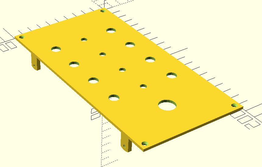
I have included two tabs for the PCB that are printed with the panel, to which I can screw the PCB using M3 screws. The tabs have small indentations for the nuts. Since I have a crappy 3D printer, those holes are not very tidy, and I use my soldering iron to convince the nuts to go where they should. And since I am an even crappier woodcraftsman than I am an electrician, the panels are set to 197 mm height in the library file to compensate for the bad measuring I did when making the case.
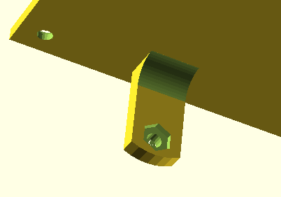
[!NOTE] The distance between the tabs that I have used depends on the pre-drilled holes of the strip boards that I like to use. Please change this distance if you have other PCBs.
Lessons from the first batch of eurorack PCBs (#05 rev1), to keep in mind for every new board.
#05: Conductor: Main Board / Rev. 2. Set the same title and revision in the schematic's title block,
so the netlist carries them too. Boards of a multi-board module or sibling modules look alike once they
are out of the bag, and a rev1 board in hand must be told apart from a rev2 one.<module>-rev<N> (e.g. 05-rev1). Start the next revision from that tag, so the ordered version can
always be recovered.I heavily relied on all material by Moritz Klein. Thanks for these awesome videos. These were the starting point for my project.
Further good sources that I recommend are:
P.S. I have built Cynthia using striboards, because I wanted to learn and prototype fast. Should you design some PCBs for any of the modules, I'd love to include them in this repository.
| Qty | Value | Footprint | References |
|---|---|---|---|
| 43 | 100k | cynthia:R SMD 0805 | R1, R2, R3, R10, R11, R12, R13, R14, R21, R23, R33, R34, R39, R40, R41, R42 +27 |
| 18 | 100nF | cynthia:C SMD 0805 | C3, C4, C5, C6, C7, C10, C11, C12, C13, C14, C15, C16, C17, C18, C19, C20 +2 |
| 12 | 10k | cynthia:R SMD 0805 | R17, R18, R35, R36, R37, R38, R57, R58, R75, R76, R77, R78 |
| 9 | TL072 | cynthia:SOIC-8_3.9x4.9mm_P1.27mm | U1, U2, U3, U4, U5, U6, U7, U8, U9 |
| 8 | 100R | cynthia:R SMD 0805 | R25, R26, R31, R32, R65, R66, R71, R72 |
| 8 | 100k | cynthia:potientiometer | RV1, RV2, RV3, RV4, RV9, RV10, RV11, RV12 |
| 8 | 100k | cynthia:trimmer | RV5, RV6, RV7, RV8, RV13, RV14, RV15, RV16 |
| 8 | 20k | cynthia:R SMD 0805 | R27, R28, R29, R30, R67, R68, R69, R70 |
| 4 | 15k | cynthia:R SMD 0805 | R22, R24, R62, R64 |
| 4 | 1N4148WS | Diode_SMD:D_SOD-323_HandSoldering | D3, D4, D5, D6 |
| 4 | 240k | cynthia:R SMD 0805 | R15, R16, R55, R56 |
| 4 | 68k | cynthia:R SMD 0805 | R19, R20, R59, R60 |
| 4 | BC847BS | Package_TO_SOT_SMD:SOT-363_SC-70-6 | Q1, Q2, Q3, Q4 |
| 4 | CV in | cynthia:3.5mm jack mono switched | J2, J3, J6, J7 |
| 4 | TestPoint | TestPoint:TestPoint_Pad_2.0x2.0mm | TP1, TP2, TP3, TP4 |
| 4 | signal in | cynthia:3.5mm jack mono switched | J4, J5, J8, J9 |
| 2 | 22uF | Capacitor_THT:CP_Radial_D6.3mm_P2.50mm | C1, C2 |
| 2 | SS14 | Diode_SMD:D_SMA | D1, D2 |
| 1 | 1k | cynthia:R SMD 0805 | R4 |
| 1 | Eurorack 10 pin header | cynthia:Eurorack Header | H1 |
| 1 | Signal out | cynthia:3.5mm jack mono switched | J1 |


cpldcpu/TouchSynth
Analog Monophonic Synthesizer with a touch keyboard. Controller by CH32V00x


OpenTaxus/opentaxus
Opentaxus is a permissively licensed set of hardware, software, and tooling to help as a starting point for customized conference badges.


It measures 70 × 100 mm and has 2 copper layers, 1.6 mm thick.
153 parts, built around the TL072, 1N4148WS, BC847BS and SS14. The full list of its parts is on this page, with links to each part's symbol and footprint where PCBKit's library has them.
From the bmurauer/cynthia repository on GitHub, at the commit this page was made from: the board is 03_quad_vca_mixer/03_quad_vca_mixer.kicad_pcb. PCBKit opens the board in the browser, with nothing to install.
Its repository states no licence, so its author keeps all rights: ask bmurauer before reusing the design.