2 layers41.1 × 41.1 mm
Leistungskreis
DevOpsOfChaos/smarthome-technikerprojekt
Lokales modulares Smart-Home-System auf ESP32-C3 und Raspberry Pi im Rahmen einer Technikerarbeit.
22 parts1

 blind-reckoning/Reckoner
Turns press-and-hold motorised blinds into Home Assistant covers. One Reckoner per blind, hidden in the wall box behind the buttons you already have.
Reckoner is an open-source printed circuit board by blind-reckoning, from the blind-reckoning/Reckoner repository on GitHub, published under the CERN-OHL-S-2.0 licence. It is a 2-layer board of 70 × 54.5 mm with 92 parts on 63 nets, routed with 516 tracks and 63 vias.
It is built around the ESP32-C6-MINI-1-N4, HLW8110 and AP2112K-3.3, with the LNK3206D-TL, BAT54S and 1N4148W among its other parts. Its parts include 27 resistors, 19 capacitors, 9 diodes, 6 connectors and 4 ICs. It belongs with the ESP32 and RISC-V boards of this library.


Turns press-and-hold motorised blinds into Home Assistant covers.
One Reckoner per blind, hidden in the wall box behind the buttons you already have.







[!CAUTION] This board switches 230 VAC mains and is not isolated. Every part of it, including the ESP32 and the programming pads, is live whenever it is connected. A mistake can kill you or start a fire inside your wall. If you are not qualified to work on mains wiring, do not build or install it. Read Safety first.
Motorised blinds with press-and-hold buttons have no idea where they are. The Reckoner sits in the wall box between those buttons and the motor, and fixes that.
| Block | Main parts |
|---|---|
| Mains input | 2 A slow-blow fuse, 275 VAC varistor; circuit ground is mains L |
| Supply | LNK3206D off-line buck to 5 V (no transformer), AP2112K-3.3 |
| Microcontroller | ESP32-C6-MINI-1: Wi-Fi 6, Bluetooth LE, Thread |
| Metering | HLW8110 and a 10 mΩ shunt: motor current and mains voltage |
| Motor relays | K1 HF46F-G switches the motor, K2 G5Q-14 picks the direction |
| Inputs | Resistor dividers and BAT54S clamps for the buttons and every mains cycle |
K2's common is fed through K1, so up and down can never be live at the same time, not even with a firmware bug or a welded contact. Both relays are held off by hardware through reset, boot and flashing.
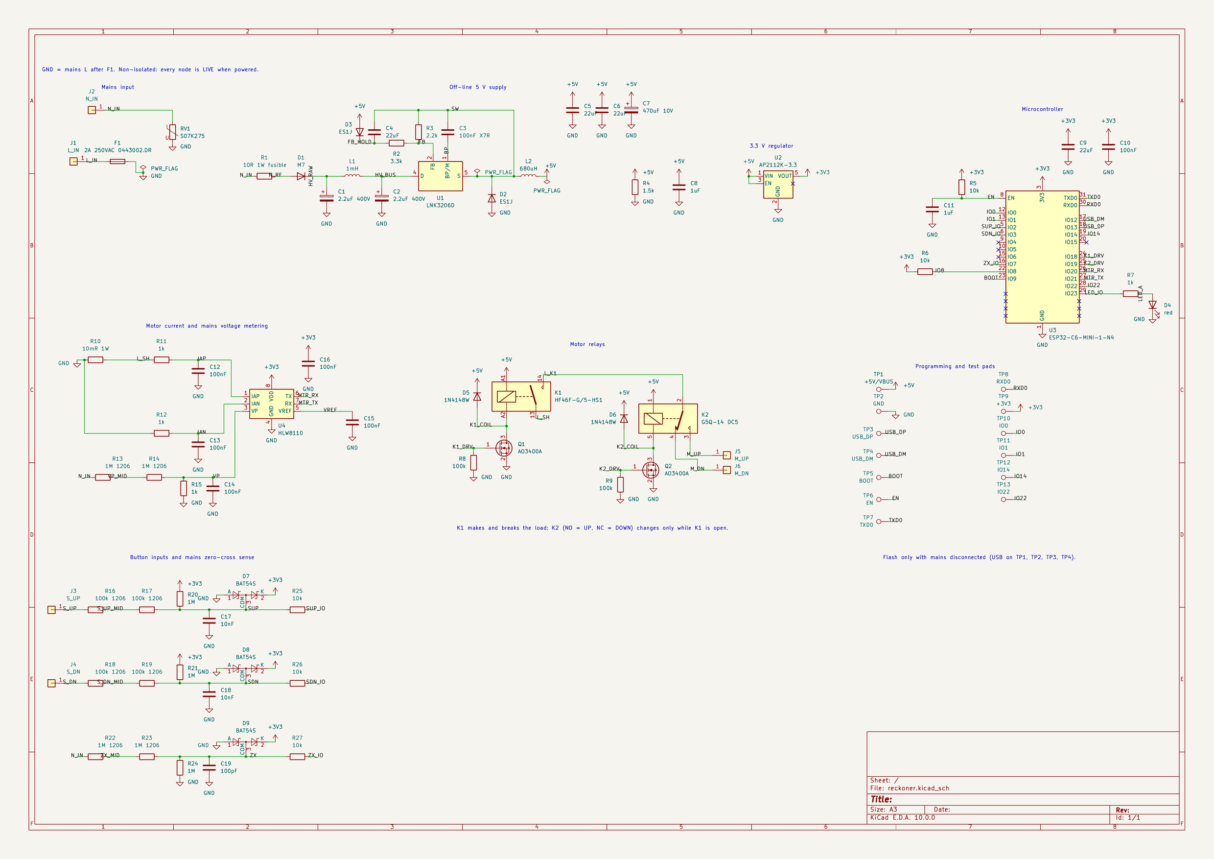
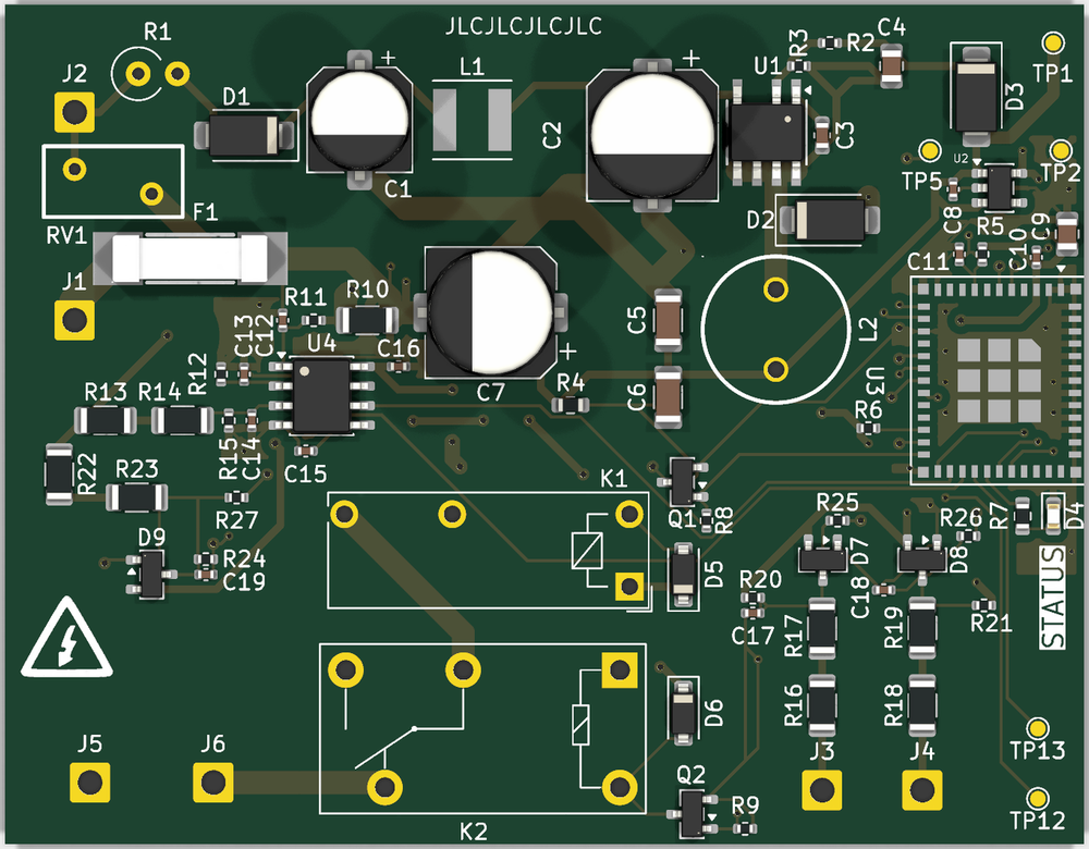
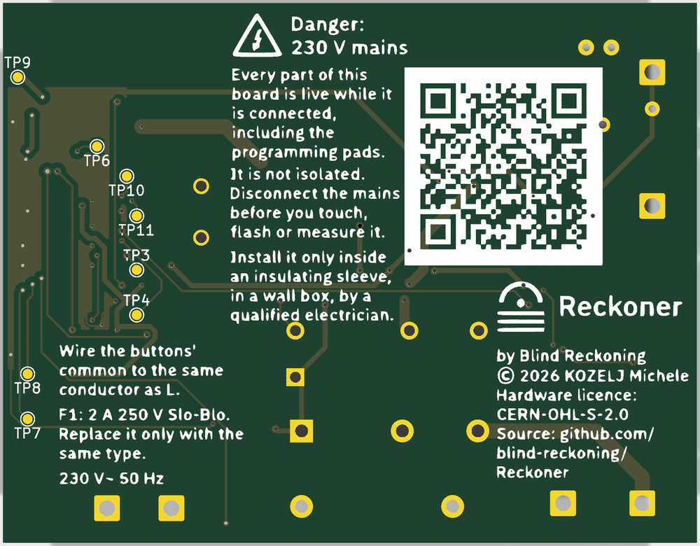
The board is 70 × 54.5 mm on two layers, routed by hand, with 3 to 5 mm between mains nodes. The production files for JLCPCB are in PCB/production/.
| Item | Qty | Supplier | Price (USD) |
|---|---|---|---|
Per-part BOM BOM/bom.csv, order lists for LCSC and Digi-Key, quote screenshots in BOM/ | 1 | — | 0.00 |
| PCB: 2 layers, 70 × 54.5 mm, 1.6 mm, green, lead-free HASL (5 boards) | 1 | JLCPCB | 6.25 |
| SMT stencil, top side, with frame | 1 | JLCPCB | 16.75 |
| Parts for one board, with LCSC minimum order quantities | 1 | LCSC | 29.24 |
| Parts for one board: U3 and R11/R12/R15 | 1 | Digi-Key | 4.77 |
| Shipping and taxes | All | 89.74 | |
| Total | 146.75 |
Shipping and taxes: JLCPCB $24.28 (after a $10 coupon), LCSC $30.17 (shipping and tariff, after $3.05 of discounts), Digi-Key $35.29 (€25.00 shipping and €6.44 VAT). The same table is in bom.csv.
[!WARNING] There is no low-voltage side. Circuit ground is mains live (L), so the ESP32, the LED, the test pads and every trace sit at 230 VAC to earth whenever L and N are connected. Only the enclosure protects you.
[!IMPORTANT] Blind Reckoning is a hobby prototype I built for Hack Club Half Life. It is not a certified product and has not been tested by any laboratory. Everything here is provided as is, without warranty. If you build, flash, test or install a Reckoner, you do so entirely at your own risk. The authors accept no responsibility for injury, death, fire or damage to property.
The Blind Reckoning "brand" is just a game. Please do not take it too seriously ;)
Designed, routed and costed; boards and parts are next to order. The enclosure (CAD/) and firmware (Firmware/) are not started.
| What | Licence |
|---|---|
Hardware: PCB/, CAD/ and BOM/bom.csv | CERN-OHL-S-2.0 |
Documentation: this README and docs/ | CC BY-SA 4.0 |
| Firmware | not written yet |
These licences apply retroactively: any copy of the hardware or documentation from any commit of this repository, including commits made before the licence files were added on 2 October 2026, is licensed under these terms.
Copyright 2026 KOZELJ Michele. Source location: https://github.com/blind-reckoning/Reckoner. If you make hardware from this source, keep the source location visible on the board or enclosure where practicable (CERN-OHL-S v2, section 4).
Not covered: the Blind Reckoning name and logos (brand/logos/, brand/symbols/), which are not licensed for reuse, so modified hardware needs its own name (see the brand book); the fonts in brand/fonts/ (SIL Open Font License 1.1); and KiCad's library symbols and footprints (KiCad library licence).
| Qty | Value | Footprint | References |
|---|---|---|---|
| 6 | 100nF | Capacitor_SMD:C_0402_1005Metric | C10, C12, C13, C14, C15, C16 |
| 6 | LOGO | LOGO | G***, G***, G***, G***, G***, G*** |
| 5 | 10k | Resistor_SMD:R_0402_1005Metric | R5, R6, R25, R26, R27 |
| 4 | 100k 1206 | Resistor_SMD:R_1206_3216Metric | R16, R17, R18, R19 |
| 4 | 1M 1206 | Resistor_SMD:R_1206_3216Metric | R13, R14, R22, R23 |
| 3 | 1M | Resistor_SMD:R_0402_1005Metric | R20, R21, R24 |
| 3 | 1k | Resistor_SMD:R_0402_1005Metric | R11, R12, R15 |
| 3 | BAT54S | Package_TO_SOT_SMD:SOT-23 | D7, D8, D9 |
| 2 | 100k | Resistor_SMD:R_0402_1005Metric | R8, R9 |
| 2 | 10nF | Capacitor_SMD:C_0402_1005Metric | C17, C18 |
| 2 | 1N4148W | Diode_SMD:D_SOD-123 | D5, D6 |
| 2 | 1uF | Capacitor_SMD:C_0402_1005Metric | C8, C11 |
| 2 | 22uF | Capacitor_SMD:C_1206_3216Metric | C5, C6 |
| 2 | 22uF | Capacitor_SMD:C_0805_2012Metric | C4, C9 |
| 2 | AO3400A | Package_TO_SOT_SMD:SOT-23 | Q1, Q2 |
| 2 | ES1J | Diode_SMD:D_SMA | D2, D3 |
| 1 | +3V3 | TestPoint:TestPoint_Pad_D1.0mm | TP9 |
| 1 | +5V/VBUS | TestPoint:TestPoint_Pad_D1.0mm | TP1 |
| 1 | 1.5k | Resistor_SMD:R_0603_1608Metric | R4 |
| 1 | 100nF X7R | Capacitor_SMD:C_0603_1608Metric | C3 |
| 1 | 100pF | Capacitor_SMD:C_0402_1005Metric | C19 |
| 1 | 10R 1W fusible | Resistor_THT:R_Axial_DIN0309_L9.0mm_D3.2mm_P2.54mm_Vertical | R1 |
| 1 | 10mR 1W | Resistor_SMD:R_1206_3216Metric | R10 |
| 1 | 1k | Resistor_SMD:R_0603_1608Metric | R7 |
| 1 | 1mH | Inductor_SMD:L_Taiyo-Yuden_NR-50xx | L1 |
| 1 | 2.2k | Resistor_SMD:R_0402_1005Metric | R3 |
| 1 | 2.2uF 400V | Capacitor_SMD:CP_Elec_6.3x9.9 | C1 |
| 1 | 2A 250VAC 0443002.DR | EasyEDA:FUSE-SMD_L10.1-W3.1 | F1 |
| 1 | 3.3k | Resistor_SMD:R_0402_1005Metric | R2 |
| 1 | 3.9uF 400V | Capacitor_SMD:CP_Elec_8x10 | C2 |
| 1 | 470uF 10V | Capacitor_SMD:CP_Elec_8x10 | C7 |
| 1 | 680uH | EasyEDA:IND-TH_BD9.5-P5.20-D0.6 | L2 |
| 1 | AP2112K-3.3 | Package_TO_SOT_SMD:SOT-23-5 | U2 |
| 1 | BOOT | TestPoint:TestPoint_Pad_D1.0mm | TP5 |
| 1 | EN | TestPoint:TestPoint_Pad_D1.0mm | TP6 |
| 1 | ESP32-C6-MINI-1-N4 | RF_Module:ESP32-C6-MINI-1 | U3 |
| 1 | G5Q-14 DC5 | Relay_THT:Relay_SPDT_Omron-G5Q-1 | K2 |
| 1 | GND | TestPoint:TestPoint_Pad_D1.0mm | TP2 |
| 1 | HF46F-G/5-HS1 | Relay_THT:Relay_SPST_Omron_G5NB | K1 |
| 1 | HLW8110 | Package_SO:SOIC-8_3.9x4.9mm_P1.27mm | U4 |
| 1 | IO0 | TestPoint:TestPoint_Pad_D1.0mm | TP10 |
| 1 | IO1 | TestPoint:TestPoint_Pad_D1.0mm | TP11 |
| 1 | IO14 | TestPoint:TestPoint_Pad_D1.0mm | TP12 |
| 1 | IO22 | TestPoint:TestPoint_Pad_D1.0mm | TP13 |
| 1 | LNK3206D | Package_SO:PowerIntegrations_SO-8C | U1 |
| 1 | L_IN | Connector_Wire:SolderWire-0.75sqmm_1x01_D1.25mm_OD2.3mm | J1 |
| 1 | M7 | Diode_SMD:D_SMA | D1 |
| 1 | M_DN | Connector_Wire:SolderWire-0.75sqmm_1x01_D1.25mm_OD2.3mm | J6 |
| 1 | M_UP | Connector_Wire:SolderWire-0.75sqmm_1x01_D1.25mm_OD2.3mm | J5 |
| 1 | N_IN | Connector_Wire:SolderWire-0.75sqmm_1x01_D1.25mm_OD2.3mm | J2 |
| 1 | RXD0 | TestPoint:TestPoint_Pad_D1.0mm | TP8 |
| 1 | S07K275 | EasyEDA:RES-TH_L9.0-W4.6-P5.00-D0.6-S1.60 | RV1 |
| 1 | S_DN | Connector_Wire:SolderWire-0.75sqmm_1x01_D1.25mm_OD2.3mm | J4 |
| 1 | S_UP | Connector_Wire:SolderWire-0.75sqmm_1x01_D1.25mm_OD2.3mm | J3 |
| 1 | TXD0 | TestPoint:TestPoint_Pad_D1.0mm | TP7 |
| 1 | USB_DM | TestPoint:TestPoint_Pad_D1.0mm | TP4 |
| 1 | USB_DP | TestPoint:TestPoint_Pad_D1.0mm | TP3 |
| 1 | red | LED_SMD:LED_0603_1608Metric | D4 |
It measures 70 × 54.5 mm and has 2 copper layers, 1.6 mm thick.
92 parts, built around the ESP32-C6-MINI-1-N4, HLW8110, AP2112K-3.3 and LNK3206D-TL. The full list of its parts is on this page, with links to each part's symbol and footprint where PCBKit's library has them.
From the blind-reckoning/Reckoner repository on GitHub, at the commit this page was made from: the board is PCB/reckoner.kicad_pcb and its schematic PCB/reckoner.kicad_sch. PCBKit opens the board in the browser, with nothing to install.
Its repository publishes it under the CERN-OHL-S-2.0 licence: you may reuse it on that licence's terms (keep the author's notice, and for a copyleft licence share your changes alike).
DevOpsOfChaos/smarthome-technikerprojekt
Lokales modulares Smart-Home-System auf ESP32-C3 und Raspberry Pi im Rahmen einer Technikerarbeit.

pavan-firmware/EH-Master-Repo
This directory contains the KiCad Schematic and PCB Design Project for the EH Smart Switch (3X / 4X Channel with BL0942 Metering).

nathanfraske/CEC-Platform
ONE board file, kept current by the wave (owner directive 2026-07-25: "the current best should be placed into a candidate folder per board and kept current with only one board ideally so we have a reference").

eerdemgundogdu/avtech-agv-main
Software and carrier PCB design for a line-following forklift AGV built by CU AVTECH for the Sanayide Robotik Uygulamalar 2026 competition.


MBI-Ignitions/MBI_Ignition_Systems
Repository for uploading ignition system information

kuvychko/universal-nixie-display
Six IN-14 Nixie tubes, an A101 dekatron and an ESP32 touchscreen in one desktop display: a clock, timer and toy, and a numeric display for a computer over USB.
