
4 layers161 × 100 mm

 bl-instr/MAX31865-cube
The MAX31865 Cube is a compact, wireless instrumentation module in the Blinky-Lite Instrumentation Platform. It is designed to perform two precision four-terminal resistance measurements for temperature sensing, then…
Blinky cube is an open-source printed circuit board by bl-instr, from the bl-instr/MAX31865-cube repository on GitHub, published under the MIT licence. It is a 2-layer board of 86.6 × 67.4 mm with 12 parts on 45 nets, routed with 96 tracks and 9 vias.
It is built around the MAX31865AAP+. Its parts include 3 ICs, 3 connectors, 2 resistors, 1 capacitor and 1 diode. It belongs with the RP2040 boards of this library.
Two-channel, precision four-terminal resistance measurement for accurate temperature sensing.
| Enclosure | PCB |
|---|---|
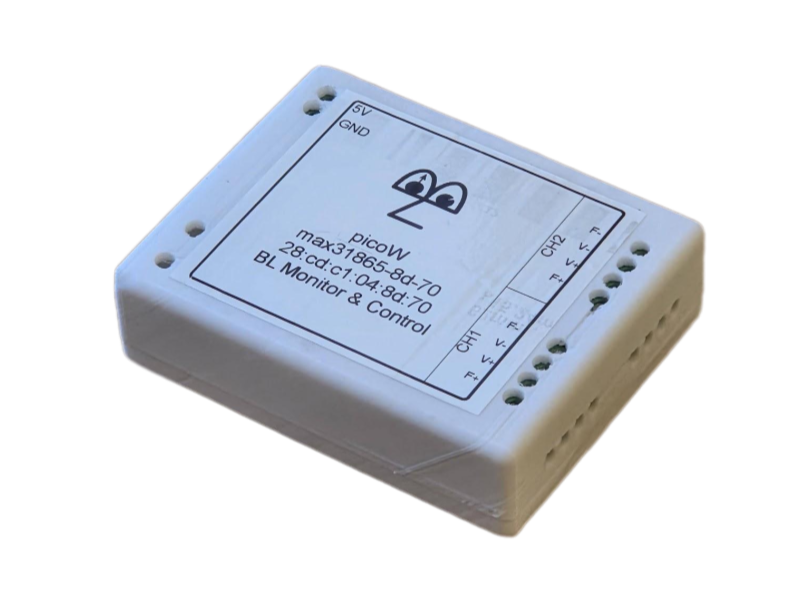 | 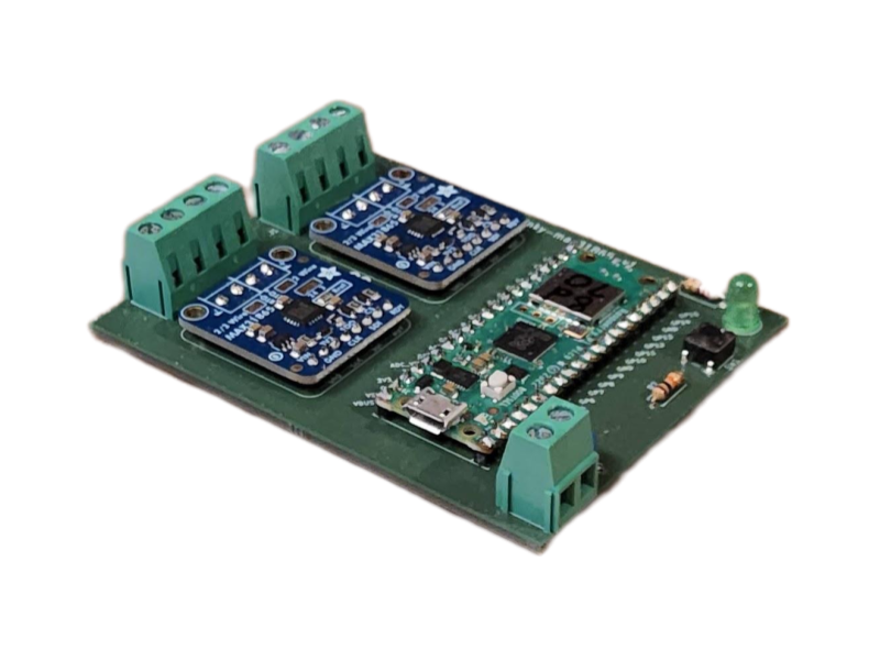 |
The MAX31865 Cube is a compact, wireless instrumentation module in the Blinky-Lite Instrumentation Platform. It is designed to perform two precision four-terminal resistance measurements for temperature sensing, then communicate resistance and calculated temperature data to a central Blinky-Lite control system.
Four-terminal measurement removes the effect of lead resistance, which is necessary for precision resistance thermometry, including cryogenic applications. Each channel uses a MAX31865 resistance-to-digital converter with 15-bit resolution and resistance precision of 0.13 Ω.
For accurate temperature conversion across a wide operating range, each channel evaluates a seventh-order polynomial fit. Blinky-Lite downloads the coefficients to the cube and supports log-log, linear-linear, log-linear, and linear-log fitting modes.
Built around the Raspberry Pi Pico W / RP2040, the module uses 2.4 GHz Wi-Fi and MQTT publish/subscribe communication. This event-driven approach supports distributed deployments without wired data connections and enables Blinky-Lite to use device information for recording, notifications, visualisation, and machine-protection workflows.
| Specification | Details |
|---|---|
| Primary function | Precision four-terminal resistance thermometry and temperature characterisation |
| Sensor / interface | Four-terminal resistance temperature sensors using MAX31865 resistance-to-digital converter chips |
| Channels | Two independent four-terminal resistance temperature-measurement channels |
| Resolution | 15 bits |
| Resistance precision | 0.13 Ω |
| Temperature conversion | Seventh-order polynomial fit per channel; coefficients downloaded from Blinky-Lite |
| Polynomial fit modes | Log-log, linear-linear, log-linear, and linear-log |
| Measurement excitation | 100 ms pulsed measurements at a user-defined interval |
| Noise reduction | User-configurable averaging count per channel |
| Inputs / outputs | 5 mm screw terminals for four-terminal sensor wiring |
| Power input | 5 V DC via 5 mm screw terminals |
| Wireless | 2.4 GHz Wi-Fi |
| Communication | MQTT publish/subscribe protocol |
| Controller | Raspberry Pi Pico W / RP2040 |
| PCB dimensions | 67 mm × 86 mm |
| Enclosure and mounting | 72 mm × 93 mm × 25 mm; DIN Mod4-compatible enclosure with removable DIN-rail mount |
| Platform | Blinky-Lite Instrumentation Platform |
The firmware targets the Raspberry Pi Pico W / RP2040 using the Arduino-Pico board support.
The firmware is released under the MIT License, giving users broad permission to study, modify, and adapt the code for their own applications. The open hardware design can likewise be customised to suit site-specific requirements. The firmware uses the open-source Arduino-BlinkyPicoW library, which is also available under the MIT License.
The MAX31865 Cube uses MQTT to publish resistance measurements, calculated temperatures, and alarm events. This event-driven model avoids conventional polling and enables prompt control-system responses to changing thermal conditions. In a typical deployment, the device connects by Wi-Fi to the network and communicates through an MQTT broker. Blinky-Lite represents it as an integrated instrumentation node and can use its information for recording, display, notification, alarms, and machine-protection logic.
| Qty | Value | Footprint | References |
|---|---|---|---|
| 2 | MAX31865 | MAX31865:MAX31865 | U2, U3 |
| 2 | Screw_Terminal_01x04 | TerminalBlock:TerminalBlock_bornier-4_P5.08mm | J1, J2 |
| 1 | 10k | Resistor_THT:R_Axial_DIN0207_L6.3mm_D2.5mm_P7.62mm_Horizontal | R2 |
| 1 | 1uF | Capacitor_THT:C_Disc_D4.3mm_W1.9mm_P5.00mm | C1 |
| 1 | 220 | Resistor_THT:R_Axial_DIN0207_L6.3mm_D2.5mm_P7.62mm_Horizontal | R1 |
| 1 | LED | LED_THT:LED_D5.0mm | D1 |
| 1 | LOGO | blinkyLiteLogo:blinkyLiteLogo | G*** |
| 1 | Pico | MCU_RaspberryPi_and_Boards:RPi_Pico_SMD_TH | U1 |
| 1 | SW_Push | Button_Switch_THT:SW_PUSH_6mm | SW1 |
| 1 | Screw_Terminal_01x02 | TerminalBlock:TerminalBlock_bornier-2_P5.08mm | J3 |
It measures 86.6 × 67.4 mm and has 2 copper layers, 1.6 mm thick.
12 parts, built around the MAX31865AAP+. The full list of its parts is on this page, with links to each part's symbol and footprint where PCBKit's library has them.
From the bl-instr/MAX31865-cube repository on GitHub, at the commit this page was made from: the board is schematics/kiCad/blinky-cube.kicad_pcb and its schematic schematics/kiCad/blinky-cube.kicad_sch. PCBKit opens the board in the browser, with nothing to install.
Its repository publishes it under the MIT licence: you may reuse it on that licence's terms (keep the author's notice, and for a copyleft licence share your changes alike).

jorticus/lupa-espresso
Espresso controller firmware for an E61-grouphead style espresso machine


DepBo/AquaCare
AquaCare là hệ thống theo dõi và quản lý nuôi trồng thủy sản, gồm ứng dụng web, ứng dụng di động và backend kết nối dữ liệu cảm biến với thiết bị trong ao/bể.

Gr3yh0und/brewingstation
Automate your brew day: ESP32 + induction cooktop + PID control, talking MQTT to CraftBeerPi.

KozaMateusz/TemperatureManagementGUI
Graphical user interface to controll the temperature in a chamber.

N5GEH/n5geh.devices.iot_wa_aio
IoT-AIO is a wireless adapter for developing IoT applications for Industrial and Building Automation Systems based on the Espressif chipset ESP32.
