4 layers56.5 × 99.8 mm
My custom miner
PrinceYadav78/My_custom_miner
Mines crypto runs python pck bitaxetool to use this
135 partsMIT

 bitaxeorg/bitaxeMax17
bitaxe based on the BM1397 ASIC from the Antminer S17
BitaxeMax is an open-source printed circuit board by bitaxeorg, from the bitaxeorg/bitaxeMax repository on GitHub, published under the CERN-OHL-S-2.0 licence. It is a 4-layer board of 56.5 × 99.8 mm with 153 parts on 100 nets, routed with 1,193 tracks and 210 vias.
It is built around the ESP32-S3-WROOM-1-N8, DS4432U+ and RT9080-33GJ5, with the TPS40305DRC, TXB0104RGYR and CSD17311Q5 among its other parts. Its parts include 51 capacitors, 30 resistors, 14 ICs, 9 connectors and 2 transistors. It belongs with the ESP32 boards of this library.


Closed Source is Antithetical to Bitcoinbitaxe is the first fully open source hardware Bitcoin ASIC miner.
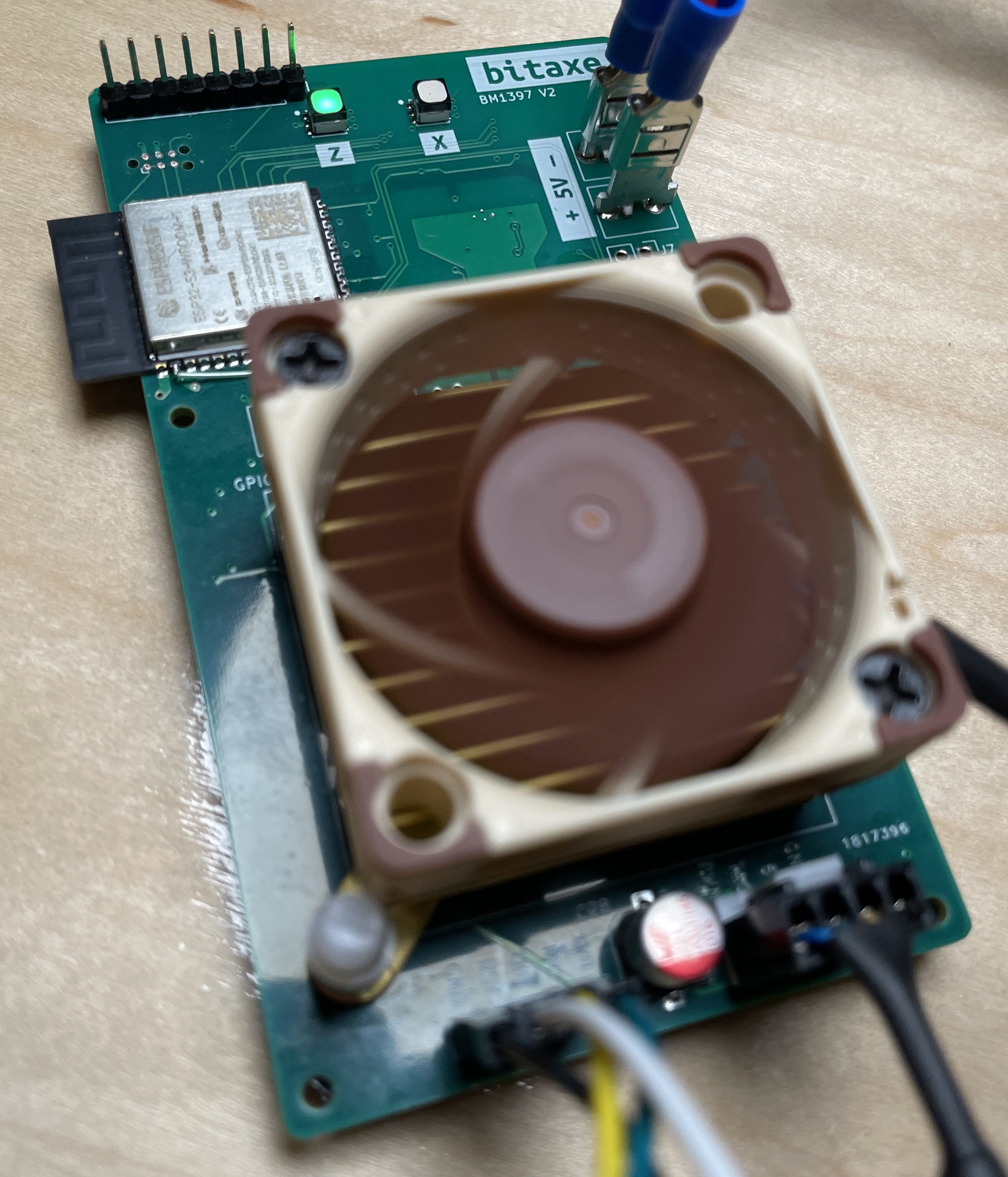
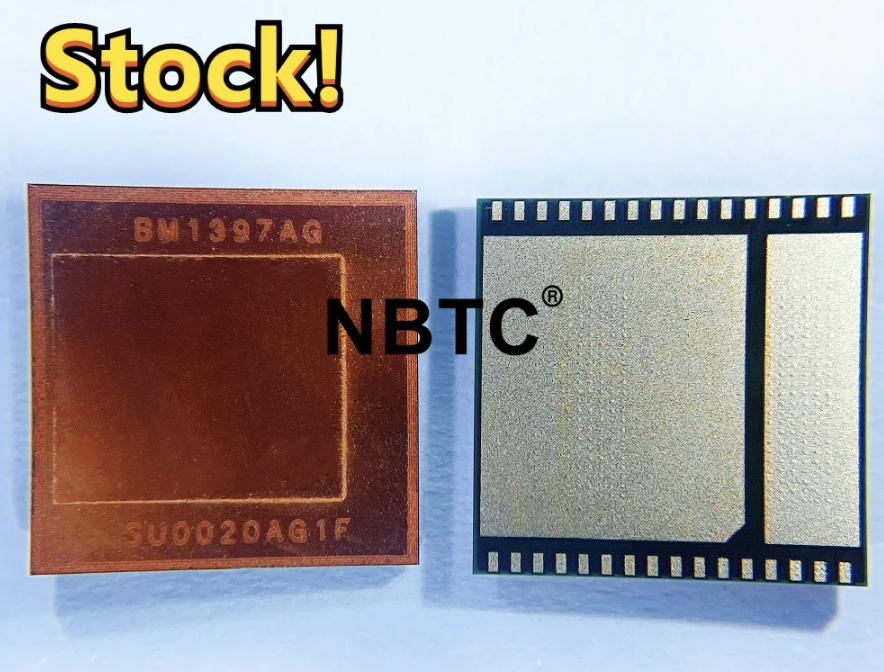
i2c_test branch for a basic firmware to init all hardware (besides BM1397)nonce_checking branch for the latest developments in the ESP32 minerOne of the best ways currently to test a new bitaxe is with a usbserial adapter and cgminer running on a separate computer.
RTS line to the bitaxe RST pin. Yes, that spelling is correct.To program the onboard ESP32, you need the following tools;
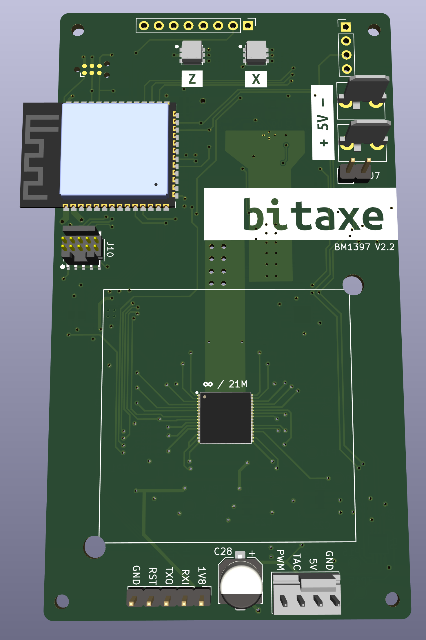
| Pin Name | Description |
|---|---|
| +5V | Main input. This should be 5V, 15W |
| GND | Main input ground |
| Qty | Value | Footprint | References |
|---|---|---|---|
| 31 | TestPoint | TestPoint:TestPoint_Pad_D1.5mm | TP1, TP2, TP10, TP11, TP12, TP13, TP14, TP15, TP16, TP17, TP18, TP19, TP21, TP22, TP23, TP24 +15 |
| 21 | 1uF | Capacitor_SMD:C_0402_1005Metric | C2, C3, C4, C10, C11, C12, C14, C15, C16, C17, C18, C24, C25, C27, C35, C44 +5 |
| 13 | 0.1uF | Capacitor_SMD:C_0402_1005Metric | C1, C7, C9, C19, C20, C21, C22, C23, C26, C29, C33, C42, C52 |
| 6 | 10k | Resistor_SMD:R_0402_1005Metric | R4, R6, R9, R20, R24, R36 |
| 4 | 0 | Resistor_SMD:R_0402_1005Metric | R2, R3, R5, R23 |
| 4 | 100 | Resistor_SMD:R_0402_1005Metric | R7, R8, R26, R27 |
| 4 | AlignmentHole | MountingHole:MountingHole_2.2mm_M2 | H1, H2, H3, H4 |
| 3 | 1k | Resistor_SMD:R_0402_1005Metric | R1, R18, R19 |
| 3 | 47uF | Capacitor_SMD:C_1210_3225Metric | C34, C36, C37 |
| 2 | 10uF | Capacitor_SMD:C_0805_2012Metric | C43, C51 |
| 2 | 261 | Resistor_SMD:R_0402_1005Metric | R28, R29 |
| 2 | 6.8pF | Capacitor_SMD:C_0402_1005Metric | C30, C31 |
| 2 | 60.4 | Resistor_SMD:R_0402_1005Metric | R21, R22 |
| 2 | CLX6E-FKC | bitaxe:CLX6E-FKC-CH1M1D1BB7C3D3 | U4, U13 |
| 2 | CSD17311Q5 | TPS40305_supply:CSD17311Q5 | Q1, Q2 |
| 2 | Conn_01x01 | TPS40305_supply:63862-1 | J1, J2 |
| 2 | MCP1824 | Package_TO_SOT_SMD:SOT-23-5 | U5, U6 |
| 2 | MountingHole | MountingHole:MountingHole_3.5mm | H5, H6 |
| 2 | SolderJumper_2_Open | Jumper:SolderJumper-2_P1.3mm_Open_RoundedPad1.0x1.5mm | JP1, JP2 |
| 1 | 1.33k | Resistor_SMD:R_0402_1005Metric | R13 |
| 1 | 1.5nF | Capacitor_SMD:C_0805_2012Metric | C41 |
| 1 | 100k | Resistor_SMD:R_0402_1005Metric | R11 |
| 1 | 100uF | Capacitor_SMD:C_1206_3216Metric | C47 |
| 1 | 150nH | TPS40305_supply:FP1005R1-R15-R | L1 |
| 1 | 180pF | Capacitor_SMD:C_0805_2012Metric | C40 |
| 1 | 19.1k | Resistor_SMD:R_0402_1005Metric | R25 |
| 1 | 1uF | Capacitor_SMD:C_0805_2012Metric | C38 |
| 1 | 220uF | TPS40305_supply:CAP_2R5TPE220MAFB | C46 |
| 1 | 220uF | Capacitor_SMD:CP_Elec_6.3x7.7 | C28 |
| 1 | 25MHz | bitaxe:O 25,0-JO32-B-1V3-1-T1-LF | U1 |
| 1 | 3.32k | Resistor_SMD:R_0402_1005Metric | R15 |
| 1 | 3.3nF | Capacitor_SMD:C_0402_1005Metric | C39 |
| 1 | 3.83k | Resistor_SMD:R_0402_1005Metric | R10 |
| 1 | 32.768kHz | bitaxe:SC32S-7PF20PPM | Y1 |
| 1 | 330uF | Capacitor_Tantalum_SMD:CP_EIA-7343-31_Kemet-D_Pad2.25x2.55mm_HandSolder | C13 |
| 1 | 4.12k | Resistor_SMD:R_0402_1005Metric | R12 |
| 1 | 4.99k | Resistor_SMD:R_0402_1005Metric | R14 |
| 1 | 470pF | Capacitor_SMD:C_0402_1005Metric | C32 |
| 1 | 470pF | Capacitor_SMD:C_0805_2012Metric | C45 |
| 1 | 80k | Resistor_SMD:R_0402_1005Metric | R16 |
| 1 | BM1397_mode1 | bitaxe:BM1397 | IC1 |
| 1 | Conn_01x02 | Connector_PinHeader_2.54mm:PinHeader_1x02_P2.54mm_Vertical | J7 |
| 1 | Conn_01x04 | bitaxe:470531000 | J4 |
| 1 | Conn_01x04 | Connector_PinHeader_2.54mm:PinHeader_1x04_P2.54mm_Vertical | J9 |
| 1 | Conn_01x05 | Connector_PinHeader_2.54mm:PinHeader_1x05_P2.54mm_Vertical | J3 |
| 1 | Conn_01x08 | Connector_PinHeader_2.54mm:PinHeader_1x08_P2.54mm_Vertical | J6 |
| 1 | DNP | Resistor_SMD:R_0402_1005Metric | R17 |
| 1 | DS4432U+ | Package_SO:TSSOP-8_3x3mm_P0.65mm | U10 |
| 1 | EMC2101 | Package_SO:TSSOP-8_3x3mm_P0.65mm | U7 |
| 1 | ESP32-S3-WROOM-1 | Espressif:ESP32-S3-WROOM-1 | U12 |
| 1 | FTSH-105-01-F-DV-K_SAI | bitaxe:FTSH-105-01-F-DV-K | J10 |
| 1 | G*** | kibuzzard-6387EEBE | kibuzzard-6387EEBE |
| 1 | G*** | kibuzzard-63D74789 | kibuzzard-63D74789 |
| 1 | G*** | kibuzzard-6387EECB | kibuzzard-6387EECB |
| 1 | G*** | kibuzzard-6392B1E5 | kibuzzard-6392B1E5 |
| 1 | INA260 | Package_SO:TSSOP-16_4.4x5mm_P0.65mm | U8 |
| 1 | JTAG Source | Jumper:SolderJumper-3_P1.3mm_Bridged2Bar12_Pad1.0x1.5mm | JP4 |
| 1 | RT9080-33GJ5 | bitaxe:RT9080-33GJ5 | U11 |
| 1 | SN74AXC1T45DBVR | bitaxe:SN74AXC1T45 | U3 |
| 1 | SolderJumper_2_Bridged | Jumper:SolderJumper-2_P1.3mm_Bridged2Bar_RoundedPad1.0x1.5mm | JP3 |
| 1 | TC2030-IDC | Connector:Tag-Connect_TC2030-IDC-NL_2x03_P1.27mm_Vertical | J5 |
| 1 | TPS40305 | TPS40305_supply:TPS40305 | U9 |
| 1 | TXB0104RGYR | bitaxe:TXB0104 | U2 |
It measures 56.5 × 99.8 mm and has 4 copper layers, 1.6 mm thick.
153 parts, built around the ESP32-S3-WROOM-1-N8, DS4432U+, RT9080-33GJ5 and TPS40305DRC. The full list of its parts is on this page, with links to each part's symbol and footprint where PCBKit's library has them.
From the bitaxeorg/bitaxeMax repository on GitHub, at the commit this page was made from: the board is bitaxeMax.kicad_pcb and its schematic bitaxeMax.kicad_sch. PCBKit opens the board in the browser, with nothing to install.
Its repository publishes it under the CERN-OHL-S-2.0 licence: you may reuse it on that licence's terms (keep the author's notice, and for a copyleft licence share your changes alike).
PrinceYadav78/My_custom_miner
Mines crypto runs python pck bitaxetool to use this


bitaxeorg/bitaxeGamma
Bitaxe based on the BM1370 from the S21 Pro


256foundation/emberone00-pcb
KiCAD design files for the emberOne/00 hashboard
