
2 layers128.3 × 50.8 mm
CD32 Controller
BleuLlama/AmigaSchematics
Schematics of various Commodore Amiga related items
33 parts58MIT

 biomurph/Absolute_Encoder_Board
Why would you want an absolute encoder over a quadrature encoder?
Absolute Encoder is an open-source printed circuit board by biomurph, from the biomurph/Absolute_Encoder_Board repository on GitHub, published under the CERN-OHL-P-2.0 licence. It is a 2-layer board of 69 × 30 mm with 22 parts on 16 nets, routed with 96 tracks and 8 vias.
It is built around the 74LS165PC. Its parts include 9 resistors, 2 connectors, 2 switches, 1 capacitor and 1 IC.
#DEVELOPMENT BRANCH
Welcome to the Open-Source Absolute Encoder Board Repository. Here you will find hardware designs and files that support the Absolute Encoder. The GrayCode Arduino Library is available for installation via the Arduino IDE, just do a search for GrayCode in the Libraries Manager
Encoders come in different types. Most people are familiar with quadrature encoders, which use two pins that change state sequentially in different order depending on the direction of rotation. One of the limitations of quadrature is that a microcontroller needs to be paying attention (usually with pin-change interrupts) in order to keep track of each step and count accordingly CW or CCW steps. In certain applications, the need for interrupts and constant attention to the encoder pin change can be limiting. Enter the Absolute encoder. This device can have 3 or more pins that maintain their coded state to show their rotational position. That means that any time you want to, you can read the encoder pins and get the correct positon without having to always keep track. Wikipedia has a great Gray Code Page for those who want to deep dive.
Why would you want an absolute encoder over a quadrature encoder?
Those two reasons are good enough for me!
The encoders in this project use Gray code, also know has Reflected Binary code. It was invented in order to avoid electro-mechanical glitches in rotary circuits. A rotary switch, for example that has 4 pins which output a binary coded decimal (BCD) may have more than one pin (bit) changing state during a transition between positions. This means that it can be possible to misread the rotational position at the transition point between rotational sections. With Gray code, only one bit is changed during each rotational transition, making it far more stable and resistant to glitches and bad readings. Here is a chart of Decimal, Binary, and Grey encoding.
| Decimal | Binary | Gray |
|---|---|---|
| 0 | 0000 | 0000 |
| 1 | 0001 | 0001 |
| 2 | 0010 | 0011 |
| 3 | 0011 | 0010 |
| 4 | 0100 | 0110 |
| 5 | 0101 | 0111 |
| 6 | 0110 | 0101 |
| 7 | 0111 | 0100 |
| 8 | 1000 | 1100 |
| 9 | 1001 | 1101 |
| 10 | 1010 | 1111 |
| 11 | 1011 | 1110 |
| 12 | 1100 | 1010 |
| 13 | 1101 | 1011 |
| 14 | 1110 | 1001 |
| 15 | 1111 | 1000 |
Here's another rendering of the Gray code, arranged in a circle. This is the bit pattern of the dial, counting up when it is traveled clockwise.
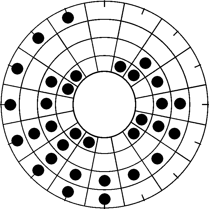
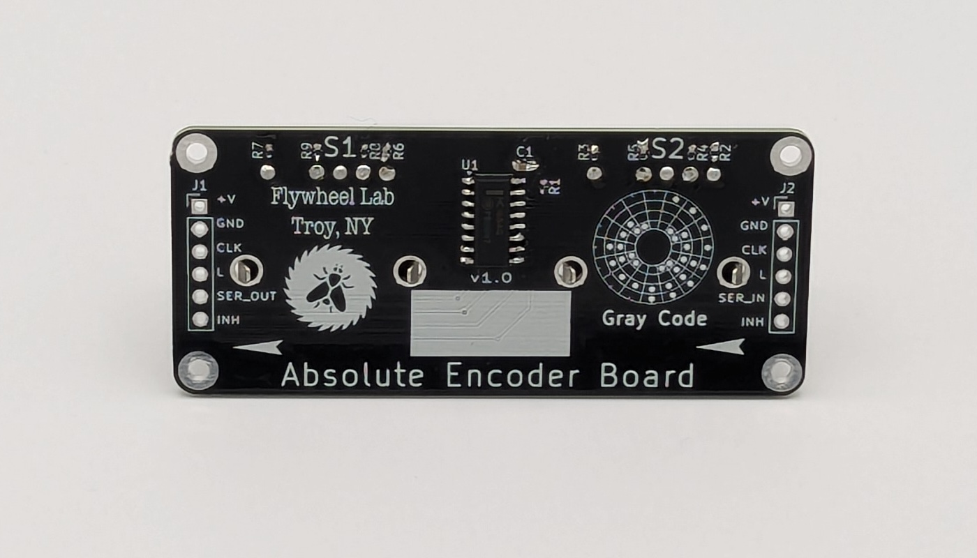
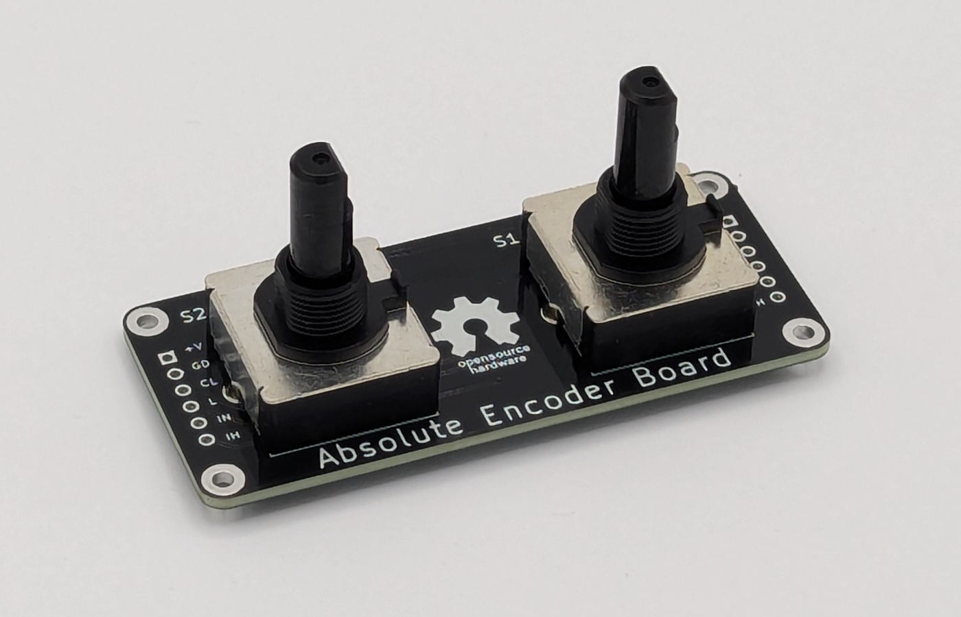
The hardware is in prototype stage. I am using the PAC18R Absolute Encoder from Bourns. They have a 5 pin output, 4 signal pins and 1 common pin, and come in 8 or 16 switch positions. These encoders have detents, which means they 'snap' into rotational position much like an old CRT television set knob does. The board design will carry 2 encoders and use a PISO shift register to read their positions. SW1 position data is in the low nibble, and SW2 data is in the high nibble. These boards can be daisy-chained, and the GrayCode library is designed to read off as many encoder boards as you have connected. The distance between the encoders is 35mm (1 3/8") on center.
The PAC18R comes in 8, 12, and 16 position variants. I have not seen the 12 position switch widely available, but the GrayCode library will handle it if you come across one. The shafts on them are 6mm diameter and flatted D type. The flatted side, if you are relying on it, is positioned differently relative to the 0 (zero) position. Here's a diagram showing where the flatted position of the shaft is at position 0 for each switch relative to the PCB.
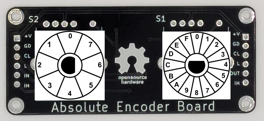
NOTE: The 12 position variant has the same flatted D orientation as the 16 position variant
There are 6 pins on each end of the board which allow for daisy-chaining mulitiple boards together. The Inhibit pin is pulled LOW on the board, so you don't need to use it unless you need to use it (HIGH is Inhibit, LOW is Hibit). The pinout on the left edge is as follows:
| Pin Name | Function |
|---|---|
| +V | Positive Voltage Input: 3V to 6V |
| GND | Connect to Voltage Ground |
| CLK | Shift Register Clock Pin |
| L | Shift Register Load Pin |
| SER_OUT | Shift Register Serial Out Pin |
| INH | Shift Register Inhibit Pin |
The only difference with the pinout on the right edge is the SER_IN pin. When daisy-chaining, connect the +V, GND, CLK, L pins, and the SER IN of the first board to the SER OUT of the next board, and so on.
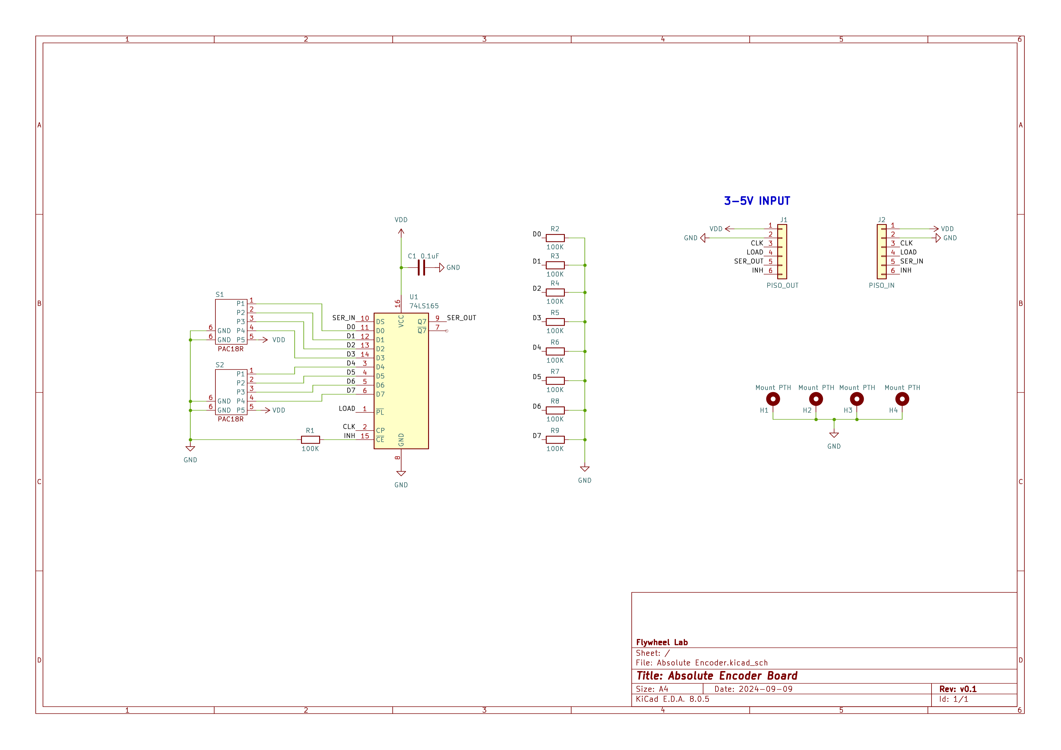
Here is the schematic
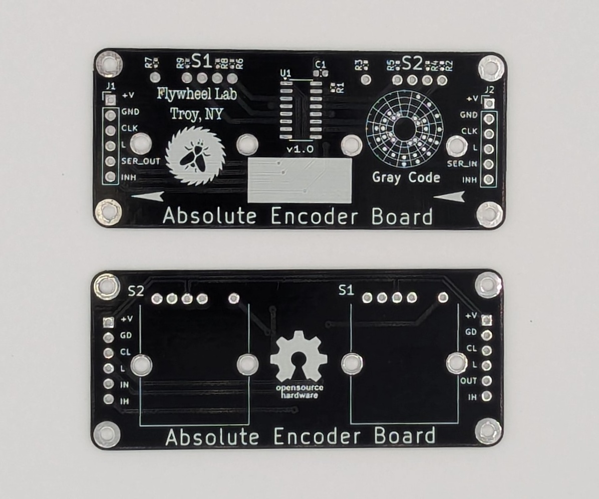
Here is a photo of the production ready prototype

Absolute Encocder Documentation © 2024 by Joel Murphy is licensed under CC BY 4.0
| Qty | Value | Footprint | References |
|---|---|---|---|
| 9 | 100K | Resistor_SMD:R_0402_1005Metric | R1, R2, R3, R4, R5, R6, R7, R8, R9 |
| 4 | Mount PTH | MountingHole:MountingHole_2.2mm_M2_Pad_TopBottom | H1, H2, H3, H4 |
| 2 | ~ | Flywheel:PAC18R | S1, S2 |
| 1 | 0.1uF | Capacitor_SMD:C_0603_1608Metric | C1 |
| 1 | 74LS165 | Package_SO:SOIC-16_3.9x9.9mm_P1.27mm | U1 |
| 1 | LOGO | Flywheel:Flywheel_Logo | G*** |
| 1 | LOGO | Flywheel:GrayCodeWheel | G*** |
| 1 | LOGO | Flywheel:oshwa-logo-gear | G*** |
| 1 | PISO_IN | Connector_PinHeader_2.54mm:PinHeader_1x06_P2.54mm_Vertical | J2 |
| 1 | PISO_OUT | Connector_PinHeader_2.54mm:PinHeader_1x06_P2.54mm_Vertical | J1 |
It measures 69 × 30 mm and has 2 copper layers, 1.6 mm thick.
22 parts, built around the 74LS165PC. The full list of its parts is on this page, with links to each part's symbol and footprint where PCBKit's library has them.
From the biomurph/Absolute_Encoder_Board repository on GitHub, at the commit this page was made from: the board is Hardware/Absolute Encoder.kicad_pcb and its schematic Hardware/Absolute Encoder.kicad_sch. PCBKit opens the board in the browser, with nothing to install.
Its repository publishes it under the CERN-OHL-P-2.0 licence: you may reuse it on that licence's terms (keep the author's notice, and for a copyleft licence share your changes alike).
BleuLlama/AmigaSchematics
Schematics of various Commodore Amiga related items


dankar/altair8800
What started as a Intel 8080 emulator turned into a Altair 8800 emulator with associated hardware for a front panel.


Xeraster/32bit_486_motherboard
A completely DIY 486 motherboard. Even the chipset is a DIY fpga thing. This version has a 32 bit front side bus and a 16 bit ISA bis

ytmytm/1551-rePico
Commodore 1551 disk-drive replacement for Plus/4, C16 and C116: Pico2 + 6510T + CPLD in a Pi1551-III case, host via tcbm2sd. Firmware/GCR derived from 1541-rePico.

ruenahcmohr/esp_01Expand32
esp-01 (esp8266) IO expander, 16 output, 16 input = 32
