2 layers150 × 100 mm
Maze kiCad
billtsol/Maze
This project demonstrates how to use an Arduino board, IR sensors, and a motor driver shield to create a maze-solving robot.
39 parts2

 billtsol/Follow-The-Line1
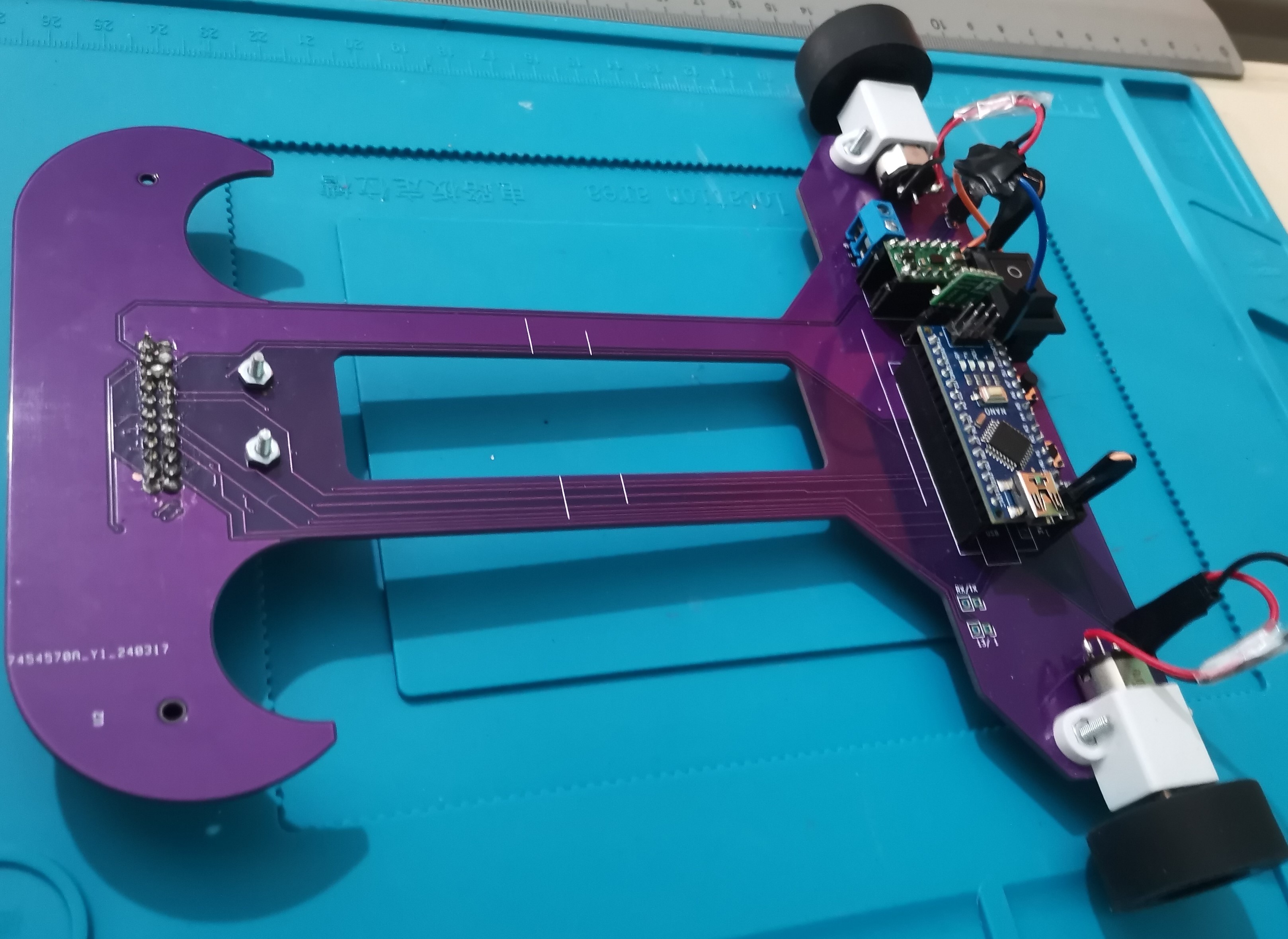
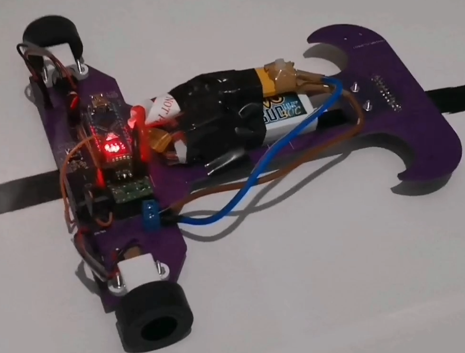
This project is an example of how to use an Arduino board, QTR reflectance sensor, and a motor driver shield to create a simple follow-the-line robot.
Follow The Line is an open-source printed circuit board by billtsol, from the billtsol/Follow-The-Line repository on GitHub. It is a 2-layer board of 191 × 151 mm with 23 parts on 40 nets, routed with 400 tracks and 46 vias.
It is built around the DRV8835DSS, L7805 and RB141C1100. Its parts include 8 connectors, 2 resistors, 2 ICs and 1 switch. It belongs with the robots and motor control boards and the AVR (ATmega, ATtiny) boards of this library.


This project is an example of how to use an Arduino board, QTR reflectance sensor, and a motor driver shield to create a simple follow-the-line robot.
To build this project, you will need the following components:
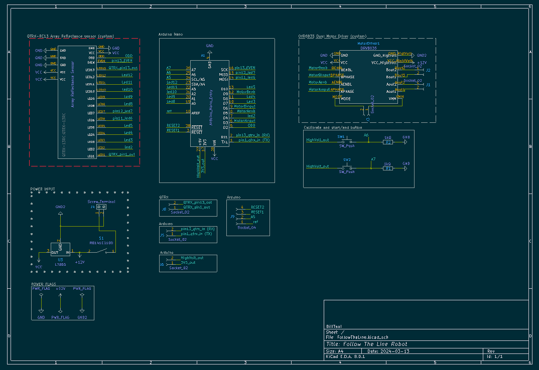
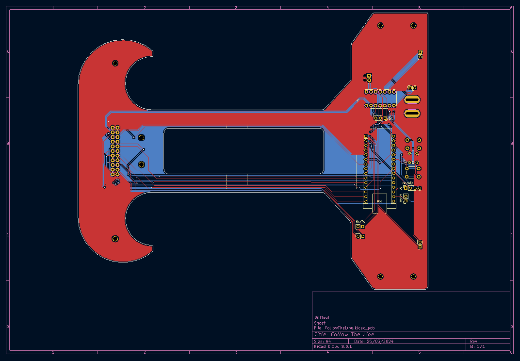
The code for this project is available in the follow_the_line.ino file.
You can also open the qtr_xA_example.ino file that includes an example of how to use the QTR reflectance sensor as an analog sensor to detect the position of a line.
follow_the_line.ino file.If the robot does not follow the line correctly, you may need to adjust the threshold values in the code or adjust the position of the QTR reflectance sensor.
Add some LEDs to make the car follow the line in the dark: By adding some LEDs to the front of the robot, it can detect the line even in low light conditions. The LEDs can be programmed to turn on when the QTR sensor detects the line and turn off when it doesn't. This feature can improve the robot's performance in darker environments.
Add some obstacle sensors to avoid objects in line: By adding some obstacle sensors to the sides of the robot, it can detect if there are any obstacles in its path and avoid them while staying on the line. This feature can improve the safety of the robot and prevent it from crashing into objects while following the line.
| Qty | Value | Footprint | References |
|---|---|---|---|
| 6 | , , , , , | ||
| 6 | Socket_02 | Connector_PinSocket_2.54mm:PinSocket_1x02_P2.54mm_Vertical | J1, J2, J3, J5, J6, J18 |
| 2 | 1kΩ | Resistor_THT:R_Axial_DIN0204_L3.6mm_D1.6mm_P5.08mm_Horizontal | R1, R2 |
| 2 | SW_Push | Button_Switch_THT:SW_PUSH_6mm | A6, A7 |
| 1 | Arduino_Nano_Every | Module:Arduino_Nano | A1 |
| 1 | Array Reflectance Sensor | QTRX-13RC:QTRX-13RC | U2 |
| 1 | DRV8835 | Library:DRV8835 | MotorDriver1 |
| 1 | L7805 | Connector_PinSocket_2.54mm:PinSocket_1x03_P2.54mm_Vertical | U3 |
| 1 | RB141C1100 | RB141C1100:SW_RB141C1100 | S1 |
| 1 | Screw_Terminal | TerminalBlock_Phoenix:TerminalBlock_Phoenix_MPT-0,5-2-2.54_1x02_P2.54mm_Horizontal | J4 |
| 1 | Socket_04 | Connector_PinSocket_2.54mm:PinSocket_1x04_P2.54mm_Vertical | J9 |
billtsol/Maze
This project demonstrates how to use an Arduino board, IR sensors, and a motor driver shield to create a maze-solving robot.

benja47012/Robot-de-seguridad
Robot de seguridad con diversas funciones, planteado con un protocolo I2C.

louisonmalinge/Projet-Velux
Dans ce Git, vous trouverez les fichiers ayant permis de réaliser le projet Velux, avec ses différentes versions.


biomimetics/MRIRobot_PCB
PC boards for MRI robogt control, specifically for STM32 motherboard

Khoapham2004/ESP32-to-ESP-NOW-Control
The second repository contains the hardware design of the robot. It is mostly based on the 2025 version, with updated sensors, the BTS signal removed from the previous design, and a PCB that primarily uses SMD…


HarvardURC/Pacbot
Repository for the Harvard Undergraduate Robotics Club's Pacbot team
It measures 191 × 151 mm and has 2 copper layers, 1.6 mm thick.
23 parts, built around the DRV8835DSS, L7805 and RB141C1100. The full list of its parts is on this page, with links to each part's symbol and footprint where PCBKit's library has them.
From the billtsol/Follow-The-Line repository on GitHub, at the commit this page was made from: the board is FollowTheLine_kiCad/FollowTheLine.kicad_pcb and its schematic FollowTheLine_kiCad/FollowTheLine.kicad_sch. PCBKit opens the board in the browser, with nothing to install.
Its repository states no licence, so its author keeps all rights: ask billtsol before reusing the design.