2 layers50.8 × 50.8 mm

 biancanev/levitas_pcb
PCB files for LeviTAS board
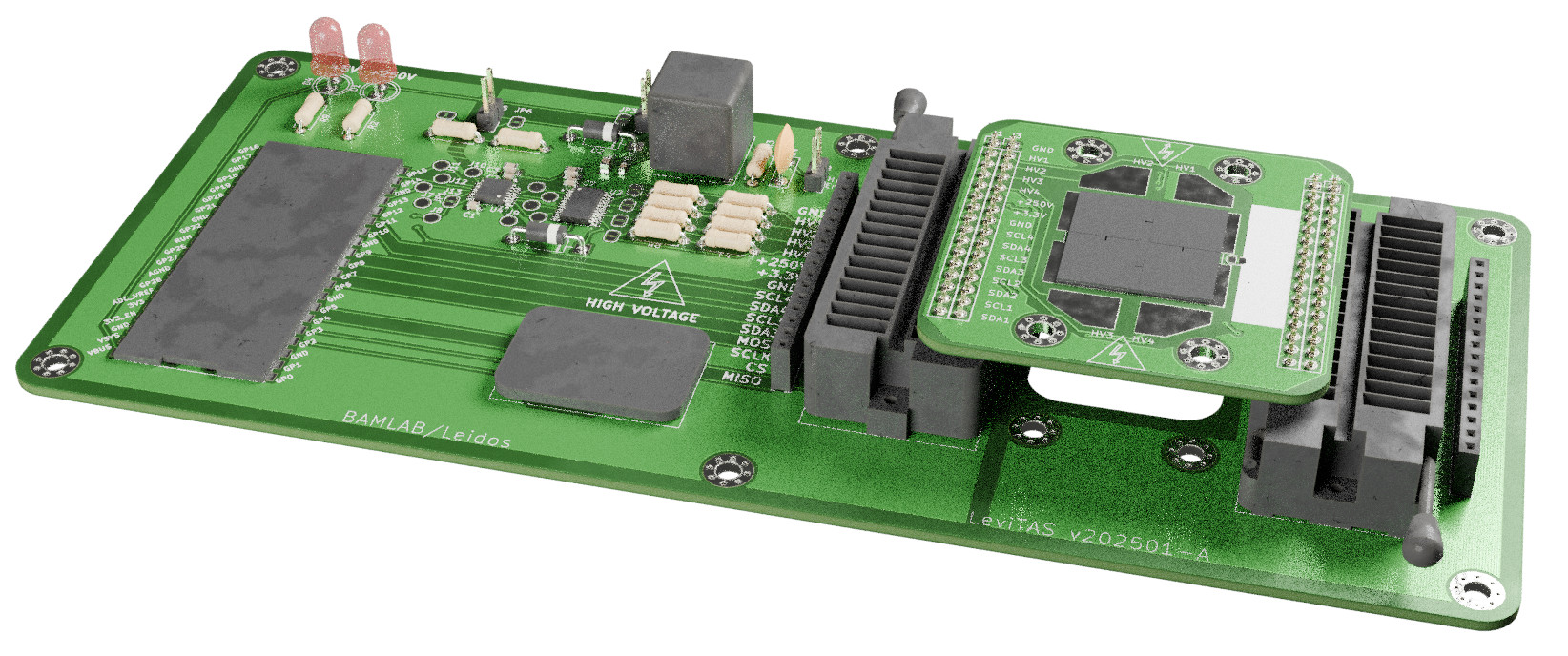
Levitas v2 is an open-source printed circuit board by biancanev, from the biancanev/levitas_pcb repository on GitHub. It is a 4-layer board of 127 × 104.1 mm with 161 parts on 134 nets, routed with 1,025 tracks and 133 vias.
Its parts include 47 capacitors, 34 resistors, 13 ICs, 12 connectors and 8 inductors.
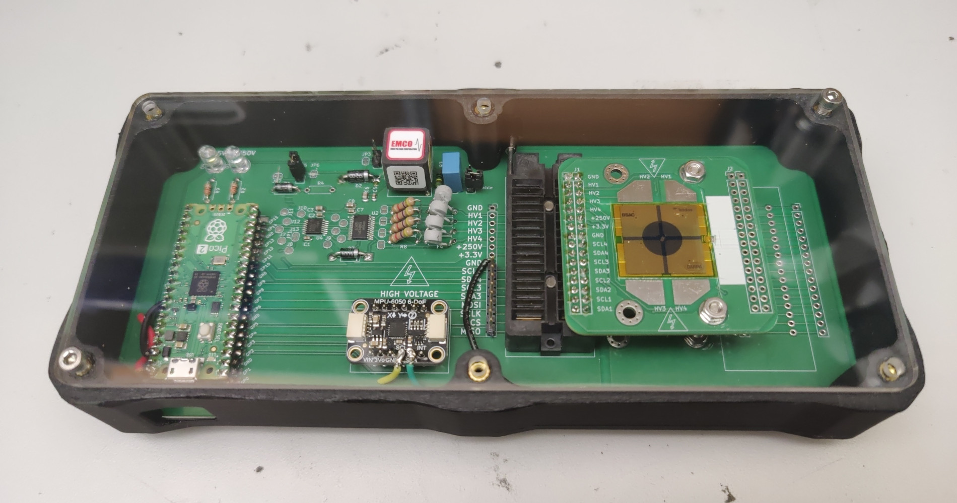
This is a PCB test platform originally built for the LeviTAS project.
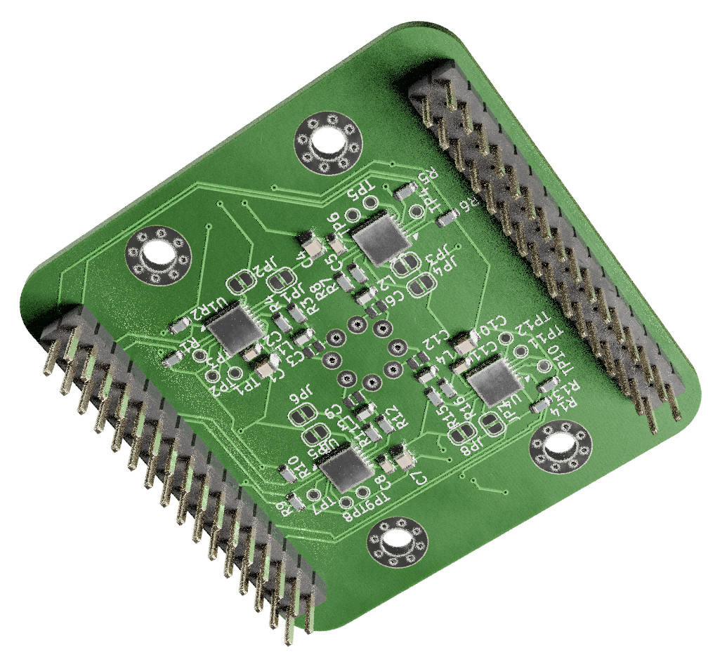
A Raspberry Pi Pico microcontroller controls four 0-240V high voltage outputs and can simultaneously read from four FDC2112 capacitance sensors. The architecture and code should be straightforward to re-engineered to add more channels.
This is how to program the microcontroller.
This project uses the Raspberry Pi RP2350 microcontroller, which is mounted to a Raspberry Pi Pico 2 dev board that we solder onto the main project PCB. The dev board is cheap and convenient because in addition to the RP2350 itself it includes flash memory, an oscillator, and power circuitry that we'd otherwise have to include anyway. The programming is the same either way.
The RP2350 is uniquely good for our use case because we need (a) four I2C buses running in parallel to read FDC2112 capacitance sensors, for which we use the PIO modules available only on the RP2040 and RP2350, and (b) we'd like floating-point math support built into the hardware, which the RP2350 has but the RP2040 does not. An FPGA might accomplish roughly the same tasks but is much more expensive and complicated to use.
Programming the RP2350 microcontroller is officially supported in C++ or MicroPython. We use C++ to more easily write programs that satisfy tight timing constraints (e.g., making a control loop as fast as possible). See the Documentation section below for links to the official documentation.
Note we're specifically using the 2.0.0 version of the SDK (because that's what we started with and haven't bothered to update it). Updating this requires updating the pico-sdk subfolder, every mention of the SDK version in other configuration files, and the version of the picotool utility used to upload the software. To minimize compilation issues, we also specifically chose to put the SDK files inside this git repo instead of requiring them to be downloaded to an external directory and linked.
Use the following steps to set up a software build environment for the Pico firmware on Linux or Windows, or follow the official getting started guide for more generic instructions.
On Linux:
firmware folder, run make build to compile code and make reload to download and run (or make to do both).On Windows:
firmware folder in VS Code. The Pi Pico extension should automatically detect this as a Pico project, and enable several commands under its quick access menu (click the extension icon on the Activity Bar, then under "Project" should be "Debug Project", "Compile Project", "Run Project (USB)", etc).build subfolder, but note that "Configure CMake" must be run first.build subfolder and prepare the compilation based on configuration information in the CMakeLists.txt file. This is run automatically when the folder is opened in VS Code if recognized by the Pico extension. NOTE: THIS MUST BE MANUALLY RE-RUN EVERY TIME YOU CHANGE CMakeLists.txt FOR THE CHANGES TO BE APPLIED!picotool command line utility). If the Pico is in BOOTSEL mode (achieved by holding down the BOOTSEL button before plugging in USB) it will probably work immediately. If not, uploading can still work if USB communication was enabled on the already-running Pico program (which it is for this software, as per CMakeLists.txt), though you might need to press "Run Project (USB)" twice.pico_enable_stdio_usb(levitas 1) to be set in CMakeLists.txt and stdio_init_all(); to be called in main.c (which they are).Inside the firmware folder:
CMakeLists.txt configures compilation, and must be manually changed to include new source code files or other settings (e.g., importing a new sublibrary for the Pico SDK)src/main.c is the main source code file and holds the main LeviTAS control loop.
src/pio_i2c.c, src/pio_i2c.h, and src/pio_i2c.pio together form a library that can run I2C communication via the Pico PIOs. src/main.c uses this library to run four I2C ports in parallel (to connect to four FDC2112 chips).CMakeLists.txt to make them the main project file instead of main.c:
src/test_fdc2112_i2c.c tests only two of the four connected FDC2112 chips by using the two hardware built-in I2C modules (instead of PIO)src/test_fdc2112_pio_i2c.c tests all four connected FDC2112 chips using the PIO library, and is almost identical to code in src/main.c.src/test_max5715_spi.c tests the MAX5715 DAC and high voltage output, and is almost identical to code in src/main.c.src/test_mpu6050_i2c.c displays data the MPU6050 accelerometer on the PCB motherboard using one of the hardware built-in I2C modules.Other files:
Makefile is used only for compiling on Linux, not for VS Code.vscode and pico_sdk_import.cmake are used only for VS Code with the official Pico VS Code extension, not on Linuxbuild subfolder is automatically generated by cmake when compiling and contains compiled executables in several formats, including UF2.The data-collection/collect-data.py and data-collection/graph-data.py Python programs in the data-collection subfolder of the main git repo can be used to automatically read the data the microcontroller sends over USB, then graph it. This provides much more useful data than manually looking at the printed output in a serial monitor.
There are several ways to upload code to a RP2040 or RP2350 chip:
Notes on the C/C++ SDK (from PDF manual):
There is a large amount of good official documentation at the following links. The most useful documentation is noted.
https://www.raspberrypi.com/documentation/microcontrollers/
RP2350 microcontroller:
Pico and Pico 2 dev boards (which are almost identical):
Programming with C/C++:
Picotool:
Raspberry Pi Debug Probe:
| Qty | Value | Footprint | References |
|---|---|---|---|
| 20 | SolderJumper_2_Bridged | Jumper:SolderJumper-2_P1.3mm_Bridged_RoundedPad1.0x1.5mm | JP1, JP2, JP3, JP4, JP5, JP10, JP11, JP12, JP13, JP14, JP15, JP16, JP17, JP18, JP20, JP22 +4 |
| 16 | 4.7k | Resistor_SMD:R_0603_1608Metric | R1, R2, R3, R4, R5, R6, R7, R8, R9, R10, R11, R12, R13, R14, R15, R16 |
| 12 | 100n | Capacitor_SMD:C_0603_1608Metric | C2, C5, C8, C11, C14, C17, C20, C23, C39, C40, C42, C46 |
| 12 | 10k | Resistor_SMD:R_1206_3216Metric | R17, R18, R19, R20, R21, R22, R23, R24, R25, R26, R27, R28 |
| 12 | 470p | Capacitor_SMD:C_0805_2012Metric | C25, C26, C27, C28, C29, C30, C31, C32, C33, C34, C35, C36 |
| 11 | 4.7u | Capacitor_SMD:C_0805_2012Metric | C1, C4, C7, C10, C13, C16, C19, C22, C41, C43, C45 |
| 8 | 18u | Inductor_SMD:L_0603_1608Metric | L1, L2, L3, L4, L5, L6, L7, L8 |
| 8 | 33p | Capacitor_SMD:C_0603_1608Metric | C3, C6, C9, C12, C15, C18, C21, C24 |
| 8 | FDC2112 | levitas_local:WSON-12-1EP_4x4mm_P0.5mm_EP2.6x3mm | U2, U3, U4, U5, U6, U7, U8, U9 |
| 8 | TestPoint | TestPoint:TestPoint_Pad_D1.0mm | TP2, TP4, TP6, TP8, TP10, TP12, TP14, TP16 |
| 4 | 5k | Resistor_THT:R_Axial_DIN0207_L6.3mm_D2.5mm_P7.62mm_Horizontal | R29, R34, R35, R36 |
| 4 | MountingHole_3.2mm_M3 | MountingHole:MountingHole_3.2mm_M3 | M3_H1, M3_H2, M3_H3, M3_H4 |
| 4 | Polyfuse | Resistor_THT:R_Axial_DIN0207_L6.3mm_D2.5mm_P7.62mm_Horizontal | F1, F2, F3, F4 |
| 4 | SolderJumper_2_Open | Jumper:SolderJumper-2_P1.3mm_Open_RoundedPad1.0x1.5mm | JP24, JP25, JP26, JP27 |
| 2 | 1u | Capacitor_SMD:C_0805_2012Metric | C37, C38 |
| 1 | 0.1u | Capacitor_SMD:C_0603_1608Metric | C39_2 |
| 1 | 10n | Capacitor_THT:C_Disc_D7.5mm_W2.5mm_P5.00mm | C44 |
| 1 | 1M | Resistor_THT:R_Axial_DIN0207_L6.3mm_D2.5mm_P7.62mm_Horizontal | R33 |
| 1 | 1N1004 | Diode_THT:D_DO-41_SOD81_P10.16mm_Horizontal | D3 |
| 1 | 220 | Resistor_THT:R_Axial_DIN0207_L6.3mm_D2.5mm_P7.62mm_Horizontal | R32 |
| 1 | 3V3_A_TP | TestPoint:TestPoint_Pad_D1.0mm | TP1 |
| 1 | 5v_TP | TestPoint:TestPoint_Pad_D1.0mm | TP3 |
| 1 | D | Diode_THT:D_DO-41_SOD81_P10.16mm_Horizontal | D2 |
| 1 | GND_TP | TestPoint:TestPoint_Pad_D1.0mm | TP5 |
| 1 | HV264 | Package_SO:TSSOP-24_4.4x7.8mm_P0.65mm | U10 |
| 1 | J_3V3_EXT | Connector_PinHeader_2.54mm:PinHeader_1x02_P2.54mm_Vertical | J23 |
| 1 | J_DA_CSM | Connector_PinHeader_2.54mm:PinHeader_1x02_P2.54mm_Vertical | J19 |
| 1 | J_DA_MOSI | Connector_PinHeader_2.54mm:PinHeader_1x02_P2.54mm_Vertical | J21 |
| 1 | J_DB_SCLK | Connector_PinHeader_2.54mm:PinHeader_1x02_P2.54mm_Vertical | J20 |
| 1 | J_HV | Connector_PinHeader_2.54mm:PinHeader_1x24_P2.54mm_Vertical | J6 |
| 1 | J_HVA | Connector_PinHeader_2.54mm:PinHeader_1x04_P2.54mm_Vertical | J3 |
| 1 | J_HVB | Connector_PinHeader_2.54mm:PinHeader_1x04_P2.54mm_Vertical | J4 |
| 1 | J_HVC | Connector_PinHeader_2.54mm:PinHeader_1x04_P2.54mm_Vertical | J5 |
| 1 | J_HV_OUT | Connector_PinHeader_2.54mm:PinHeader_1x04_P2.54mm_Vertical | J22 |
| 1 | J_MPU | Connector_PinSocket_2.54mm:PinSocket_1x08_P2.54mm_Vertical | J7 |
| 1 | Jumper_2_Bridged | Connector_PinHeader_2.54mm:PinHeader_1x02_P2.54mm_Vertical | JP23 |
| 1 | LED | LED_THT:LED_D5.0mm | D1 |
| 1 | Levitas3_Chip_40Pad_Wirebond | levitas_v3_footprint:Levitas3_Chip_40Pad_Wirebond | U1 |
| 1 | MAX5715 | Package_SO:TSSOP-14_4.4x5mm_P0.65mm | U12 |
| 1 | Q025-5C | levitas_hv:Q025-5C | U13 |
| 1 | RPI_L | Connector_PinSocket_2.54mm:PinSocket_1x20_P2.54mm_Vertical | J1 |
| 1 | RPI_R | Connector_PinSocket_2.54mm:PinSocket_1x20_P2.54mm_Vertical | J2 |
| 1 | TLV75533PDRVR | TLV755:DRV0006A | U11 |


maxlab-io/tokay-lite-pcb
Tokay AI Camera - ESP32 camera development board


baldengineer/Mega-IIe
Using the Mega II from a IIgs to make a Apple IIe compatible computer: The Mega IIe!

PCBench/PCBench
resolution = [0.5, 0.5] pcbfolder = '../PCBs/' pcbnames = ["1Bitsy1bitsy"] iters = 30 env = PCBRoutingEnv(resolution=resolution, pcbfolder=pcbfolder, pcbnames=pcbnames) obs, info = env.reset() for in range(iters): act =…

azonenberg/misc-devboards
Miscellaneous prototype hardware that wasn't major enough to warrant a dedicated repo

M0LTE/pi-transceiver
An attempt to build a complete ham radio transceiver around a Raspberry Pi


rafkhan/lowstepper
Dual phase manipulation low frequency oscillator by Okay Synthesizer.
It measures 127 × 104.1 mm and has 4 copper layers, 1.6 mm thick.
161 parts. The full list of its parts is on this page, with links to each part's symbol and footprint where PCBKit's library has them.
From the biancanev/levitas_pcb repository on GitHub, at the commit this page was made from: the board is pcb/levitas_v2/levitas_v2.kicad_pcb and its schematic pcb/adapter_pcb/adapter_pcb.kicad_sch. PCBKit opens the board in the browser, with nothing to install.
Its repository states no licence, so its author keeps all rights: ask biancanev before reusing the design.