Skip to the content
2 layers19.9 × 67.8 mmLighthouse addon, the printed circuit board in 3D

Lighthouse addon

bi-zone/offzone-hw13
Size
19.9 × 67.8 mm
Copper layers
2
Thickness
1.6 mm
Parts
11
Nets
10
Pads
26
Tracks, vias
45, 2
Routed
Yes
KiCad
KiCad 10.0 (file 20260206)
Created
2 Jun 2026
Updated
10 Aug 2026

Overview

Lighthouse addon is an open-source printed circuit board by bi-zone, from the bi-zone/offzone-hw repository on GitHub. It is a 2-layer board of 19.9 × 67.8 mm with 11 parts on 10 nets, routed with 45 tracks and 2 vias.

Its parts include 4 resistors, 2 capacitors, 2 diodes, 2 transistors and 1 connector.
README

2025/terminal_addon/README.md

terminal_addon

Для заказа платы

  • Количество проводящих слоев: 2
  • Базовый материал (Core): FR4
  • Суммарная толщина платы, мм: 1.5
  • Толщина фольги, мкм: 18 или 35
  • Финишное покрытие площадок: HASL
  • Паяльная маска: чёрная
  • Маркировка обозначений: белая

Для сборки

  • 3 светодиода 1206 Белые
  • 3 резистора 1206 220 Ом
  • Резистор 1206 1 кОм
  • Резистор 1206 100 кОм
  • Конденсатор 1206 10 мкФ
  • Микросхема LMC555
  • Коннектор PLD-6

Подробнее в terminal_addon_BOM.html

Инструкция

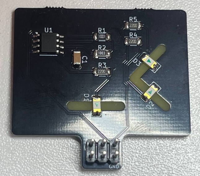
  1. Припаиваем микросхему U1. Стрелка на плате указывает расположение первого пина. Первый пин на микросхеме отмечен жирной линией. Жирная линия должна быть возле надписи U1.
  2. Припаиваем резисторы номиналом вверх. Размещать их можно в любом порядке, они не имеют полярности. Главное расставить все по своим местам.
    • R1 - 1 кОм
    • R2 - 100 кОм
    • R3, R4, R5 - 220 Ом
  3. Припаиваем светодиоды линзой вниз, соблюдая полярность. Стрелка светодиода должна указывать на белую линию.
    • D1 - смотрит вниз
    • D2, D3 - смотрят вправо
  4. Припаиваем конденсатор C1.
  5. Припаиваем коннектор.

Parts

11
QtyValueFootprintReferences
210 uFCapacitor_SMD:C_Elec_4x5.4C1, C2
2100kResistor_SMD:R_1206_3216Metric_Pad1.30x1.75mm_HandSolderR1, R4
2470Resistor_SMD:R_1206_3216Metric_Pad1.30x1.75mm_HandSolderR2, R3
2LED_WHITELED_THT:LED_D3.0mmD1, D2
2Q_PNP_BECPackage_TO_SOT_SMD:SOT-23_HandsolderingQ1, Q2
1Conn_02x02badgelife_sao_v169bis:Badgelife-Shitty-2x2J1

More from bi-zone/offzone-hw

12
  • 2 layers64.4 × 34.5 mmBoat addon, the printed circuit board in 3D

    Boat addon

    bi-zone/offzone-hw

    12 parts13
  • 2 layers48.4 × 49.9 mmSeal addon, the printed circuit board in 3D

    Seal addon

    bi-zone/offzone-hw

    11 parts13
  • 2 layers41.5 × 47.8 mmMasks addon, the printed circuit board in 3D

    Masks addon

    bi-zone/offzone-hw

    10 parts13
  • 2 layers55.9 × 38.7 mmZil addon, the printed circuit board in 3D

    Zil addon

    bi-zone/offzone-hw

    9 parts13
  • 2 layers39.6 × 48 mmCat addon, the printed circuit board in 3D

    Cat addon

    bi-zone/offzone-hw

    8 parts13
  • 2 layers47.3 × 43.9 mmBear addon, the printed circuit board in 3D

    Bear addon

    bi-zone/offzone-hw

    7 parts13
  • 2 layers30.9 × 49.4 mmLamp addon, the printed circuit board in 3D

    Lamp addon

    bi-zone/offzone-hw

    6 parts13

Similar boards

  • 2 layers60 × 30 mmController, the printed circuit board in 3D

    Controller

    google/mozc-devices

    Circuit diagrams and firmware source code for Gboard DIY keyboards

    11 parts3kApache-2.0
  • 2 layers103 × 30.5 mmTS Front Endcap, the printed circuit board in 3D

    TS Front Endcap

    EEVengers/ThunderScope

    ThunderScope GitHub Repo

    11 parts1.3kMIT
  • 2 layers26 × 30 mmExpansion Card, the printed circuit board in 3D

    Expansion Card

    FrameworkComputer/ExpansionCards

    Reference designs and documentation to create Expansion Cards for the Framework Laptop

    11 parts1.1kCC-BY-4.0
  • 2 layers53.9 × 23.2 mmBuffer, the printed circuit board in 3D

    Buffer

    hoglet67/RGBtoHDMI

    Bare-metal Raspberry Pi project that provides pixel-perfect sampling of Retro Computer RGB/YUV video and conversion to HDMI

    11 parts1kGPL-3.0
  • 2 layers10 × 20 mm2 connector Sensor Board, the printed circuit board in 3D

    2 connector Sensor Board

    hackclub/OnBoard

    💡 Join 1,000 teenagers and make your first PCB with a $100 grant!

    11 parts915
  • 2 layersFet module, the printed circuit board in 3D

    Fet module

    ByteWelder/Decktility

    A handheld PC

    11 parts855CC-BY-SA-4.0
  • 2 layers47 × 33 mmSevensegment led display module, the printed circuit board in 3D

    Sevensegment led display module

    tardate/LittleArduinoProjects

    a collection of "Little Electronic & Arduino Projects", most involving electronics or an Arduino in one way or another!

    11 parts803MIT
  • 2 layers42.5 × 36.8 mmDevboard, the printed circuit board in 3D

    Devboard

    basilfx/TRADFRI-Hacking

    Hacking IKEA TRÅDFRI products, such as light bulbs, window blinds and other accessories.

    11 parts743CC-BY-4.0

Questions

How big is the Lighthouse addon PCB?

It measures 19.9 × 67.8 mm and has 2 copper layers, 1.6 mm thick.

What parts does the Lighthouse addon use?

11 parts. The full list of its parts is on this page, with links to each part's symbol and footprint where PCBKit's library has them.

Where can I download the Lighthouse addon KiCad files?

From the bi-zone/offzone-hw repository on GitHub, at the commit this page was made from: the board is 2023/lighthouse_addon/lighthouse_addon.kicad_pcb. PCBKit opens the board in the browser, with nothing to install.

Can I use the Lighthouse addon design in my own project?

Its repository states no licence, so its author keeps all rights: ask bi-zone before reusing the design.