2 layers218.5 × 159.5 mm

 bfarago/B3-38A
B3-38A Russian Millivoltmeter
JA972 is an open-source printed circuit board by bfarago, from the bfarago/B3-38A repository on GitHub, published under the LGPL-2.1 licence. It is a 2-layer board of 160 × 100 mm with 118 parts on 61 nets.
Its parts include 55 resistors, 22 capacitors, 21 connectors, 8 transistors and 7 diodes.
B3-38A or V3-38A Russian Millivoltmeter
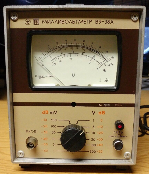
This repository contains all the collected informations regarding the old russian millivoltmeter instrument. The goal to collect datasheets, schematics, etc.
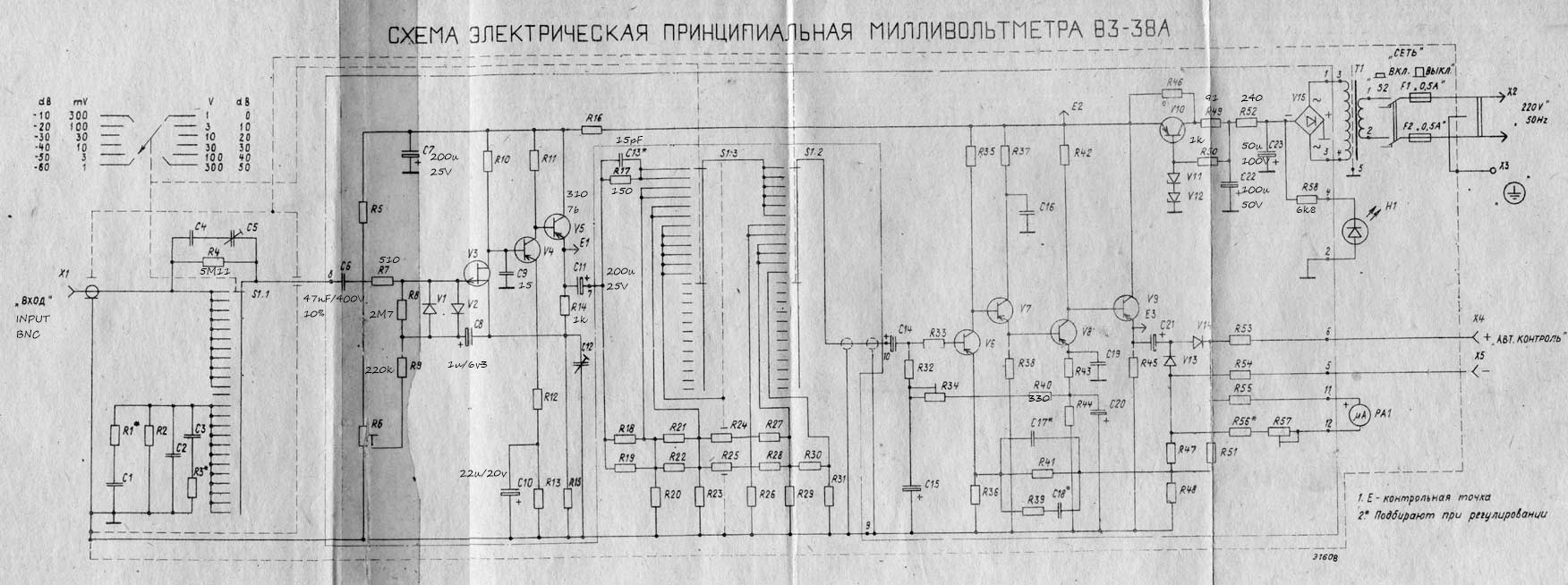
Millivoltmeter V3-38A (V3 38A, V338A, b3-38a, b338a, b3 38a)
Designed to measure the rms AC voltage sine wave of 0.1 mV to 300 V in the frequency range from 20 Hz to 5 MHz. The span value of 1 mV, 3mV, 10mV, 30mV, 100mV, 300mV, 1V, 3V, 10V, 30V, 100V and 300V The basic error of ± 2,5%
Millivoltmeter V3-38A is designed to measure the rms AC voltage sine wave of 0.1 mV to 300 V in the frequency range from 20 Hz to 5 MHz. The operating conditions of use of the instrument Millivoltmeter V3-38A: ambient temperature from 10 ° to 35 ° C; relative humidity. air 80% at 25 ° C, atmospheric pressure from 86 to 106 kPa (650 to 800 mm Hg. st.) mains (220 ± 22), frequency (50 ± 0,5) Hz . Technical Data is a Measurement range of the instrument voltages from 300V to 100mkV overlapping ranges with upper limits of 1 mV, 3mV, 10mV, 30mV, 100mV, 300mV, 1V, 3V, 10V, 30V, 100V and 300V. Instrument measures the voltage in the frequency range from 20 Hz to 5 MHz . The range of frequencies of the device Millivoltmeter V3-38A has a working range of frequencies: I from 45 Hz to 1 MHz (on); II from 20 to 45 Hz (except); III St.. 1 to 3 MHz (on); IV St.. 3 to 5 MHz (inclusive). Frequency of calibration of 1 kHz. Primary instrument error, expressed as a percentage of the upper limit established by sub-band measurements, no more than ± 2,5%. Instrument error Millivoltmeter V3-38A in the working frequency regions, expressed as a percentage of the upper limit of the established sub-band, and the change of readings within the operating frequency ranges with respect to the frequency of calibration readings in percent, do not exceed the values shown in Table. 1.
Table 1: The limits of permissible errors (beyond the assumed changes of reading),%
| Subranges | I.: 45Hz- 1 MHz | II.: 20 - 45 Hz | III.: 1 - 3 MHz | IV.: 3 - 5 MHz |
|---|---|---|---|---|
| 1 mV-300mV | ± 2,5 % | ± 4,0 (± 4,0) % | ± 4,0 (± 4,0) % | ± 6,0 (± 6,0) % |
| 1V-300V | ± 2,5 % | ± 4,0 (± 4,0) % | ± 6,0 (± 6,0) % | ± 6,0 (± 6,0) % |
Change readings, caused by changes in temperature. Ambient air from the normal to any temperature within the operating temperature range does not exceed the basic error for every 10 ° C change in temperature. Change readings Millivoltmeter V3-38A, expressed as a percentage of the upper limit established by sub-band, rejecting the shape of the measured voltage from the sinusoidal (THD less than 20%) is less than half the value of the harmonic content in percent. The deviation of the index from scratch, due to the intrinsic noise does not exceed 5% of the upper limit established by sub-band measurements with closed-circuit input. The device retains its specifications within the rules, if its input DC voltage is not more than 250-V Response time the device is less than 4 seconds. Millivoltmeter V3-38A save tons of basic error handling five times after exposure to stress, but not more than 600 V. Active impedance device, measured at a frequency of 45 Hz, less than 5 megohms at subbands upper limits 1-300mV and at least 4 Mohms subbands upper limits in 1-300 Input capacitance unit is not more than 25 pF subbands upper limits of 1-300 mV and not more than 15 pF subbands upper limits of 1-300 W. The capacity of each of the connecting cable is not more than 80 pF. Warm-up time 15 min. Millivoltmeter V3-38A retains its specifications when powered from the mains AC voltage (220 ± 22) V (50 ± 0,5) Hz. The power consumed by the network at a nominal voltage not exceeding 6 VA. Device allows continuous operation in the working conditions for 8 hours
Unit weight Millivoltmeter V3-38A or less than 3.2 kg.
| Qty | Value | Footprint | References |
|---|---|---|---|
| 7 | 3107B | Package_TO_SOT_THT:TO-92_HandSolder | Q1, Q2, Q4, Q6, Q7, Q8, Q10 |
| 6 | 1k | Resistor_SMD:R_0603_1608Metric_Pad1.05x0.95mm_HandSolder | R14, R38, R39, R47, R50, R51 |
| 5 | 240 | Resistor_SMD:R_0603_1608Metric_Pad1.05x0.95mm_HandSolder | R20, R23, R26, R29, R52 |
| 5 | 357 | Resistor_SMD:R_0603_1608Metric_Pad1.05x0.95mm_HandSolder | R19, R22, R25, R28, R30 |
| 4 | 56k | Resistor_SMD:R_0603_1608Metric_Pad1.05x0.95mm_HandSolder | R18, R21, R24, R27 |
| 4 | KD522B | Diode_SMD:D_MELF-RM10_Universal_Handsoldering | D1, D2, D13, D14 |
| 3 | P5 | Connector_Pin:Pin_D0.7mm_L6.5mm_W1.8mm_FlatFork | J19, J20, J21 |
| 3 | x | Capacitor_THT:CP_Radial_D5.0mm_P2.50mm | C17, C18, C19 |
| 2 | 110 | Resistor_SMD:R_0603_1608Metric_Pad1.05x0.95mm_HandSolder | R33, R37 |
| 2 | 12V | Diode_SMD:D_MELF-RM10_Universal_Handsoldering | D11, D12 |
| 2 | 1M | Resistor_SMD:R_0603_1608Metric_Pad1.05x0.95mm_HandSolder | R53, R54 |
| 2 | 2,49k | Resistor_SMD:R_0603_1608Metric_Pad1.05x0.95mm_HandSolder | R55, R56 |
| 2 | 2k2 | Resistor_SMD:R_0603_1608Metric_Pad1.05x0.95mm_HandSolder | R42, R45 |
| 2 | 3k | Resistor_SMD:R_0603_1608Metric_Pad1.05x0.95mm_HandSolder | R11, R13 |
| 2 | 510 | Resistor_SMD:R_0603_1608Metric_Pad1.05x0.95mm_HandSolder | R7, R44 |
| 2 | 5k6 | Resistor_SMD:R_0603_1608Metric_Pad1.05x0.95mm_HandSolder | R10, R35 |
| 2 | P10 | Connector_Pin:Pin_D0.7mm_L6.5mm_W1.8mm_FlatFork | J9, J10 |
| 2 | P7 | Connector_Pin:Pin_D0.7mm_L6.5mm_W1.8mm_FlatFork | J7, J8 |
| 2 | PGM_SWITCH2 | Connector_Pin:Pin_D0.7mm_L6.5mm_W1.8mm_FlatFork | J3, J5 |
| 2 | SW_Rotary12 | Connector_IDC:IDC-Header_2x07_P2.54mm_Vertical | SW2, SW3 |
| 1 | 0,047uF/400V/10% | Capacitor_THT:C_Axial_L5.1mm_D3.1mm_P15.00mm_Horizontal | C6 |
| 1 | 10 | Resistor_SMD:R_0603_1608Metric_Pad1.05x0.95mm_HandSolder | R36 |
| 1 | 100 | Resistor_SMD:R_0603_1608Metric_Pad1.05x0.95mm_HandSolder | R41 |
| 1 | 100u/50v | Capacitor_THT:CP_Radial_D13.0mm_P2.50mm | C22 |
| 1 | 100u/6v3 | Capacitor_SMD:CP_Elec_6.3x5.4_Nichicon | C15 |
| 1 | 15 | Resistor_SMD:R_0603_1608Metric_Pad1.05x0.95mm_HandSolder | R43 |
| 1 | 15+-10%/ M47 | Capacitor_THT:C_Rect_L10.0mm_W3.0mm_P7.50mm_FKS3_FKP3 | C9 |
| 1 | 15+-10%/ M47 | Capacitor_THT:C_Rect_L9.0mm_W2.7mm_P7.50mm_MKT | C13 |
| 1 | 150 | Resistor_SMD:R_0603_1608Metric_Pad1.05x0.95mm_HandSolder | R17 |
| 1 | 150 10% | Capacitor_SMD:C_0603_1608Metric_Pad1.05x0.95mm_HandSolder | C3 |
| 1 | 1600 500V 5% | Capacitor_THT:CP_Axial_L10.0mm_D6.0mm_P15.00mm_Horizontal | C1 |
| 1 | 165 | Resistor_SMD:R_0603_1608Metric_Pad1.05x0.95mm_HandSolder | R31 |
| 1 | 1k5 | Potentiometer_THT:Potentiometer_Bourns_3266P_Horizontal | RV57 |
| 1 | 1u/6v3 | Capacitor_SMD:CP_Elec_3x5.3 | C8 |
| 1 | 2/7 | Capacitor_SMD:C_Trimmer_Murata_TZB4-B | C5 |
| 1 | 200u/25V | Capacitor_SMD:CP_Elec_4x5.4 | C7 |
| 1 | 200u/25v | Capacitor_SMD:CP_Elec_5x5.8 | C11 |
| 1 | 200u/25v | Capacitor_SMD:CP_Elec_6.3x5.4_Nichicon | C14 |
| 1 | 200u/25v | Capacitor_THT:CP_Radial_D5.0mm_P2.50mm | C21 |
| 1 | 21,8 | Resistor_SMD:R_0603_1608Metric_Pad1.05x0.95mm_HandSolder | R3 |
| 1 | 220k | Potentiometer_THT:Potentiometer_Bourns_3266P_Horizontal | RV34 |
| 1 | 220k | Resistor_SMD:R_0603_1608Metric_Pad1.05x0.95mm_HandSolder | R9 |
| 1 | 22k | Resistor_SMD:R_0603_1608Metric_Pad1.05x0.95mm_HandSolder | R32 |
| 1 | 22u/20v | Capacitor_SMD:CP_Elec_4x5.8 | C10 |
| 1 | 2700 500V 5% | Capacitor_THT:CP_Axial_L10.0mm_D6.0mm_P15.00mm_Horizontal | C2 |
| 1 | 2M7 | Resistor_SMD:R_0603_1608Metric_Pad1.05x0.95mm_HandSolder | R8 |
| 1 | 2p2 | Capacitor_SMD:C_0603_1608Metric_Pad1.05x0.95mm_HandSolder | C4 |
| 1 | 33k | Potentiometer_THT:Potentiometer_Bourns_3266P_Horizontal | RV6 |
| 1 | 33k | Resistor_SMD:R_0603_1608Metric_Pad1.05x0.95mm_HandSolder | R40 |
| 1 | 390 | Resistor_SMD:R_0603_1608Metric_Pad1.05x0.95mm_HandSolder | R16 |
| 1 | 402 | Resistor_SMD:R_0603_1608Metric_Pad1.05x0.95mm_HandSolder | R15 |
| 1 | 47k | Resistor_SMD:R_0603_1608Metric_Pad1.05x0.95mm_HandSolder | R5 |
| 1 | 50u/100v | Capacitor_THT:CP_Radial_D13.0mm_P2.50mm | C23 |
| 1 | 51 | Resistor_SMD:R_0603_1608Metric_Pad1.05x0.95mm_HandSolder | R12 |
| 1 | 55,6 | Resistor_SMD:R_0603_1608Metric_Pad1.05x0.95mm_HandSolder | R48 |
| 1 | 5M11 | Resistor_SMD:R_0603_1608Metric_Pad1.05x0.95mm_HandSolder | R4 |
| 1 | 5k11 | Resistor_THT:R_Axial_DIN0411_L9.9mm_D3.6mm_P20.32mm_Horizontal | R2 |
| 1 | 680 | Resistor_SMD:R_0603_1608Metric_Pad1.05x0.95mm_HandSolder | R46 |
| 1 | 6k8 | Resistor_SMD:R_0603_1608Metric_Pad1.05x0.95mm_HandSolder | R58 |
| 1 | 7k5 | Resistor_THT:R_Axial_DIN0414_L11.9mm_D4.5mm_P5.08mm_Vertical | R1 |
| 1 | 91 | Resistor_SMD:R_0603_1608Metric_Pad1.05x0.95mm_HandSolder | R49 |
| 1 | CTRIM | Capacitor_SMD:C_Trimmer_Murata_TZB4-B | C12 |
| 1 | Conn_Coaxial | Connector_Coaxial:MMCX_Molex_73415-1471_Vertical | J1 |
| 1 | D_Bridge_+-AA | Diode_THT:Diode_Bridge_DIP-4_W7.62mm_P5.08mm | D3 |
| 1 | E1 | Connector_Pin:Pin_D0.7mm_L6.5mm_W1.8mm_FlatFork | J6 |
| 1 | E2 | Connector_Pin:Pin_D0.7mm_L6.5mm_W1.8mm_FlatFork | J12 |
| 1 | E3 | Connector_Pin:Pin_D0.7mm_L6.5mm_W1.8mm_FlatFork | J13 |
| 1 | P1 | Connector_Pin:Pin_D0.7mm_L6.5mm_W1.8mm_FlatFork | J17 |
| 1 | P11 | Connector_Pin:Pin_D0.7mm_L6.5mm_W1.8mm_FlatFork | J11 |
| 1 | P2 | Connector_Pin:Pin_D0.7mm_L6.5mm_W1.8mm_FlatFork | J15 |
| 1 | P3 | Connector_Pin:Pin_D0.7mm_L6.5mm_W1.8mm_FlatFork | J18 |
| 1 | P4 | Connector_Pin:Pin_D0.7mm_L6.5mm_W1.8mm_FlatFork | J16 |
| 1 | P6 | Connector_Pin:Pin_D0.7mm_L6.5mm_W1.8mm_FlatFork | J14 |
| 1 | PGM_SWITCH1 | Connector_Pin:Pin_D0.7mm_L6.5mm_W1.8mm_FlatFork | J2 |
| 1 | PGM_SWITCH3 | Connector_Pin:Pin_D0.7mm_L6.5mm_W1.8mm_FlatFork | J4 |
| 1 | kp103l | Package_TO_SOT_THT:TO-18-3 | Q3 |
| 1 | x | Capacitor_THT:CP_Radial_Tantal_D4.5mm_P2.50mm | C16 |
It measures 160 × 100 mm and has 2 copper layers, 1.6 mm thick.
118 parts. The full list of its parts is on this page, with links to each part's symbol and footprint where PCBKit's library has them.
From the bfarago/B3-38A repository on GitHub, at the commit this page was made from: the board is rv_cad/JA972/JA972.kicad_pcb. PCBKit opens the board in the browser, with nothing to install.
Its repository publishes it under the LGPL-2.1 licence: you may reuse it on that licence's terms (keep the author's notice, and for a copyleft licence share your changes alike).

TweetyDaBird/Lotus-58-Classic
A split ergo linear keyboard derived from the Lily58 family

ZeroPhone/ZeroPhone-PCBs
PCB files for ZeroPhone - for gerbers and schematics, go to "Releases" tab!

BerkeleyHCI/PolymorphicBlocks
A Python-based hardware description language for PCBs for higher-level (block-diagram / system-architecture level) PCB design through libraries of directly reusable subcircuit generators.


OPRobots/FujitoraBot
Robotracer - siguelíneas de alto rendimiento; con succión, tracción brushless en sistema tetra y procesador STM32F4

richardeoin/ax
This repository contains hardware and software for the AX5043 and AX5243 radios from AxSemi (now ON Semiconductor). They are probably the same die, but the AX5243 has fewer pins.
