2 layers65 × 56 mm

 BETA-KNH/beta5
Humanoid robot repository.
Beta main is an open-source printed circuit board by BETA-KNH, from the BETA-KNH/beta repository on GitHub. It is a 4-layer board of 76 × 121 mm with 93 parts on 181 nets, routed with 1,864 tracks and 241 vias.
It is built around the 74LVC1G126Z, AP3441SHE-7B and AP2553W6, with the BNO086, M2.5 and 1N5819WS among its other parts. Its parts include 24 capacitors, 22 connectors, 16 resistors, 7 ICs and 2 diodes. It belongs with the robots and motor control boards and the Raspberry Pi (Linux) boards of this library.


BETA is an ambitious undertaking that seeks to develop a humanoid robot possessing a range of human-like capabilities, including the ability to walk, see, and communicate verbally.
Conceived in 2018, the project has undergone several transformations and upgrades over the years. Currently, it is being developed as part of the "Koło Naukowe Humanoid" student research circle. Updates on its progress and new features are regularly shared on the group's Facebook page.
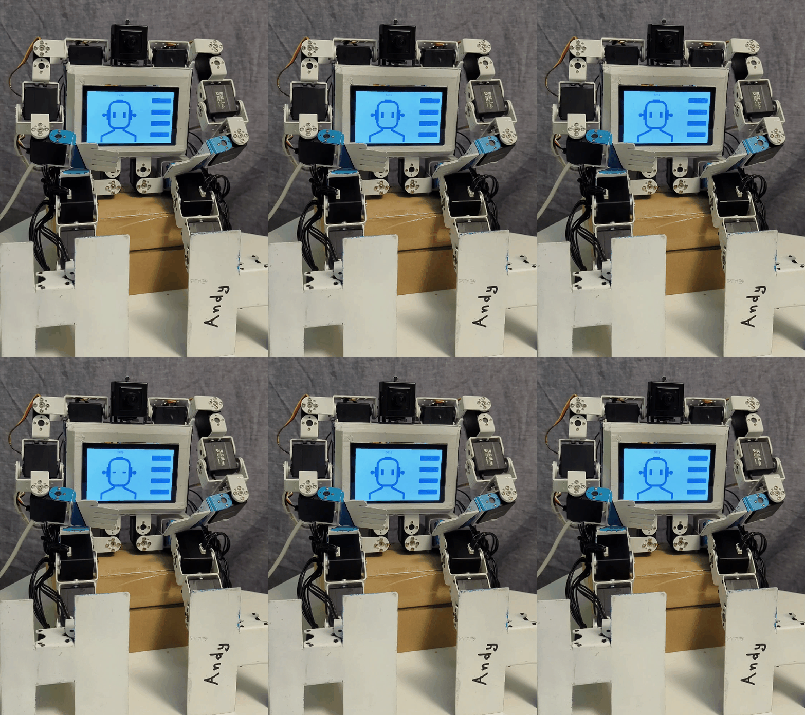
The programming language of choice for the project is Python. This decision was made because of its ease of use, large community, large number of libraries and frameworks and cross-platform compatilibity. Additionally, Python is a versatile language that can be used to develop a wide range of applications, including those that are used for the control of the robot's servos, the implementation of its vision system, and the development of its speech recognition capabilities.
The framework of the robot is composed of a hybrid of components that are either 3D-printed, purchased, or self-fabricated. The design of these parts was created in Blender, a 3D modeling software, and subsequently constructed by our team.

Additionally, a 3D printer was utilized to produce the robot's chest component.
Humanoid robot BETA is powered by a combination of two step-up voltage regulators that convert 5V to 6V and 5V to 12V respectively. While this power supply configuration is functional, it is not an ideal solution for providing power to the robot's components.
As previously stated, our project utilizes two distinct types of servos. Due to their differing control mechanisms, we have partitioned their descriptions into two distinct subcategories.
Our use of the term "pulse" refers to a conventional servo that employs a Pulse Width Modulation (PWM) signal as its control input.
Using mentioned library we've created tool to control servos with single commands. To affix the servos to the robot's framework, we employ brackets that are included in the kit alongside the servos. The Raspberry Pi's GPIO pins serve as the source of the PWM signal, which is generated by utilizing the software pigpio library. We have developed a tool utilizing the aforementioned library, which allows for the control of the servos through the use of single commands.

During the process of developing the robot, it became apparent that the existing servos were not ideally suited to our requirements, as they were prone to excessive play and struggled to maintain a fixed position. As a result, we made the decision to incorporate Bus servos in the leg joints, as these offer superior stability and control. By leveraging this approach, we can enhance the overall performance and reliability of the system, while enabling greater precision and accuracy in its movements.
In regards to the management of the second group of servos, communication is established through the utilization of the UART protocol, as the servos in question incorporate internal electronics. This approach enables efficient transmission of commands and data, as well as simplifying the wiring and control of the servos. By interfacing with the internal electronics of the servos, the system can achieve greater precision and flexibility in its movements.

For more information about Bus servo control check out our Servo library.
To achieve smooth movement of our robot, we have developed a tool that enables the sequential control of servos. The primary objective of this tool is to facilitate the coordinated movement of servos to achieve seamless motion.
The program operates by utilizing text files, which contain data regarding the angles of each servo required for a given pose. By compiling a list of various poses, complex movements can be achieved through the sequential execution of poses. To create these text files, we have developed a custom tool that allows for the adjustment of the robot to a desired pose and the subsequent saving of this pose to a text file for later use.


The software application that has been developed utilizes the PySide2 library to create a graphical user interface (GUI). The primary objective of this application is to enable the user to manage and manipulate the behavior of a robot through a touch screen interface.


For the purpose of speech-to-text, we have utilized the speech to textV website. The website is accessed through the use of the Selenium library. The library allows for the automation of the browser, which enables the implementation of the speech-to-text functionality.
One possible solution to address this issue is to utilize an application programming interface (API) that provides speech-to-text functionality. However, after careful consideration, it was determined that this approach was not optimal due to cost implications and implementation complexity. As an alternative, a solution was chosen that is both cost-effective and easy to implement, and does not impose excessive demands on computer resources.
For the purpose of pose estimation, the project team has chosen to use ArUco trackers, which are part of the OpenCV library. This is because ArUco markers are an efficient and accurate type of fiducial marker that can be easily detected and identified in image or video streams. By attaching multiple ArUco markers to the human's limbs and joints, the position and orientation of these markers can be tracked to estimate the robot's pose with a high degree of accuracy.

In order to collect information about the location and orientation of the human body's joints and calculate angles for the robot, ArUco trackers will be attached to the human body. At this time, no other solutions have been selected for pose estimation purposes.
While operating humanoid robot BETA, it is important to take the necessary safety precautions to prevent injury or damage to the robot or its surroundings. Please read the following guidelines carefully before using the robot:
Supervision: Always supervise the robot when it is in use. Do not leave the robot unattended around small children or pets.
Operating environment: Use the robot in a safe and controlled environment. Avoid using the robot near stairs, ledges, or other hazards that could cause the robot to fall or be damaged.
Power source: Only use the power source specified in the documentation. Do not use unauthorized power sources or chargers, as this could damage the robot or cause a fire.
Servo control: When controlling the robot's servos, be aware of their range of motion and potential speed. Do not exceed the recommended range or speed, as this could damage the robot or cause it to malfunction.
Maintenance: Regularly inspect the robot for wear and tear such as loose screws, frayed wires, or damaged components. If any issues are found, take the necessary steps to repair or replace the affected parts.
Transport: When transporting the robot, make sure it is securely fastened and protected from damage.
By following these safety precautions, you can help ensure the safe and reliable operation of your humanoid robot BETA.
We plan to upgrade the power supply to a more efficient and stable configuration that uses step-down voltage regulators to convert 12V to 5V and 12V to 6V respectively.
The proposed power supply solution involves the use of a 3-cell lithium-ion battery.
By using a step-down voltage regulator to convert the 12V output from the battery to 5V and 6V respectively, we can ensure a stable and efficient power supply for the robot's components. This power supply solution also provides the added benefit of making the robot battery-powered, which increases its mobility and versatility.
We are confident that this proposed power supply solution will provide a safe, efficient, and reliable source of power for Humanoid robot BETA, and we look forward to implementing this upgrade in the near future.
As part of our future development plans, we intend to upgrade the current servos with more powerful alternatives. This enhancement will enable the creation of more intricate and sophisticated movements. In addition, we plan to incorporate a more advanced control system, which will allow for the implementation of more complex behaviors and actions.
The project team is considering adding gyroscope sensors to provide a more accurate source of information for angle estimation, thus allowing the robot to replicate human movements more accurately. Furthermore, a combination of different solutions, such as ArUco trackers, 2D pose estimation, and gyroscopes, may be tested to determine which approach yields the best results.
| Qty | Value | Footprint | References |
|---|---|---|---|
| 17 | 10u | Capacitor_SMD:C_0603_1608Metric | C3, C4, C5, C6, C7, C8, C11, C13, C14, C15, C16, C17, C18, C19, C20, C21 +1 |
| 9 | 10k | Resistor_SMD:R_0603_1608Metric | R2, R3, R4, R5, R6, R13, R14, R15, R16 |
| 6 | Conn_01x02_Pin | Connector_JST:JST_PH_B2B-PH-K_1x02_P2.00mm_Vertical | J1, J19, J20, J21, J24, J25 |
| 5 | Conn_01x04_Pin | Connector_JST:JST_PH_B4B-PH-K_1x04_P2.00mm_Vertical | J14, J15, J16, J17, J26 |
| 4 | Conn_01x03_Pin | Connector_JST:JST_XH_B3B-XH-A_1x03_P2.50mm_Vertical | J10, J11, J12, J13 |
| 4 | M2.5 | MountingHole:MountingHole_2.7mm_Pad | MH9, MH10, MH11, MH12 |
| 4 | M3 | MountingHole:MountingHole_3.2mm_M3_Pad_Via | MH1, MH3, MH5, MH7 |
| 3 | 0.1u | Capacitor_SMD:C_0603_1608Metric | C1, C22, C23 |
| 3 | 100u | Capacitor_SMD:CP_Elec_6.3x5.7 | C2, C12, C24 |
| 3 | ~ | Fiducial:Fiducial_1mm_Mask2mm | FID1, FID2, FID3 |
| 2 | 2.2u | CM5IO:L_Bourns_SRP5030CC | L1, L2 |
| 2 | 74LVC1G126 | Package_TO_SOT_SMD:SOT-23-5 | U2, U4 |
| 2 | Conn_01x06_Pin | Connector_JST:JST_PH_B6B-PH-K_1x06_P2.00mm_Vertical | J22, J23 |
| 2 | Conn_01x08_Pin | Connector_JST:JST_PH_B8B-PH-K_1x08_P2.00mm_Vertical | J2, J3 |
| 2 | FFC | Connector_FFC-FPC:TE_1-84953-5_1x15-1MP_P1.0mm_Horizontal | J5, J8 |
| 1 | 100 | Resistor_SMD:R_0603_1608Metric | R12 |
| 1 | 10K 1% | Resistor_SMD:R_0603_1608Metric | R10 |
| 1 | 15k | Resistor_SMD:R_0603_1608Metric | R9 |
| 1 | 1N5819WS | Diode_SMD:D_SOD-323 | D2 |
| 1 | 2.2K 1% | Resistor_SMD:R_0603_1608Metric | R11 |
| 1 | 20k | Resistor_SMD:R_0603_1608Metric | R1 |
| 1 | 220K | Resistor_SMD:R_0603_1608Metric | R7 |
| 1 | 30K | Resistor_SMD:R_0603_1608Metric | R8 |
| 1 | 3V3 | TestPoint:TestPoint_Pad_D1.0mm | TP2 |
| 1 | 4.7nF | Capacitor_SMD:C_0603_1608Metric | C10 |
| 1 | 5V | TestPoint:TestPoint_Pad_D1.0mm | TP1 |
| 1 | AP2553W6 | Package_TO_SOT_SMD:SOT-23-6 | U7 |
| 1 | AP3441SHE-7B | Package_DFN_QFN:DFN-8-1EP_2x2mm_P0.5mm_EP1.05x1.75mm | U5 |
| 1 | BNO086 | BETA:IC_BNO086 | U3 |
| 1 | ComputeModule5-CM5 | CM5IO:Raspberry-Pi-5-Compute-Module | CM5 |
| 1 | IRLML6246TRP | Package_TO_SOT_SMD:SOT-23 | Q2 |
| 1 | LED_RED | LED_SMD:LED_0603_1608Metric | D1 |
| 1 | MAX98357A | Package_DFN_QFN:TQFN-16-1EP_3x3mm_P0.5mm_EP1.23x1.23mm | U1 |
| 1 | MMBT3906 | Package_TO_SOT_SMD:SOT-23 | Q1 |
| 1 | SolderJumper_2_Open | BETA:SolderJumper-2 | JP1 |
| 1 | TPS56624x | Package_TO_SOT_SMD:SOT-563 | U6 |
| 1 | XT60 | Connector_AMASS:AMASS_XT60-F_1x02_P7.20mm_Vertical | J18 |
The 90 most common of 93 parts.
It measures 76 × 121 mm and has 4 copper layers, 1.65 mm thick.
93 parts, built around the 74LVC1G126Z, AP3441SHE-7B, AP2553W6 and BNO086. The full list of its parts is on this page, with links to each part's symbol and footprint where PCBKit's library has them.
From the BETA-KNH/beta repository on GitHub, at the commit this page was made from: the board is hardware/kicad/beta-main/beta-main.kicad_pcb and its schematic hardware/kicad/beta-main/beta-main.kicad_sch. PCBKit opens the board in the browser, with nothing to install.
Its repository states no licence, so its author keeps all rights: ask BETA-KNH before reusing the design.


e-abdi/EK80-Seaglider
Integration of a Simrad EK80 echosounder on a Seaglider: mounting brackets and the noise suppressor interface board.

John-Nagle/ttyloopdriver
Hardware device for driving antique Teletype machines

pedalboard/pedalboard-hw
pedalboard audio midi processor open hardware

0x62b/travel-router
CM5 travel router carrier board with dual 1G ethernet, wifi

the-mr-music/OrangeCanBreakout
Board to test the MCP2517 SPI CAN controller together with the Orange Pi Zero Plus 2