2 layers45 × 23 mm
Tiny
pengshulin/mcush
MCUSH application platform (personal toolkit: firmware platform, debugger, hardware, test and application framework)
53 parts103

 BenGrumm/STM-Quadcopter3
A simple quadcopter built on the STM32F411CEU6 (black pill board) with 4 motors, a PPM receiver, ADC checking battery level and I2C communication with MPU6050 imu.
Quadcopter is an open-source printed circuit board by BenGrumm, from the BenGrumm/STM-Quadcopter repository on GitHub. It is a 4-layer board of 38.5 × 37 mm with 49 parts on 71 nets, routed with 375 tracks and 28 vias.
It is built around the STM32F411CEU6, AMS1117-3.3 and MPU-6050, with the C13 among its other parts. Its parts include 18 capacitors, 10 resistors, 9 connectors, 3 ICs and 2 diodes. It belongs with the robots and motor control boards and the STM32 boards of this library.


A simple quadcopter built on the STM32F411CEU6 (black pill board) with 4 motors, a PPM receiver, ADC checking battery level and I2C communication with MPU6050 imu.
The video below shows the initial flights with a proportional and integral control loop the Pitch and Roll axis but not on Yaw.
Below is the schematic, high level routing and manufactured PCB created after prototyping the functionality.
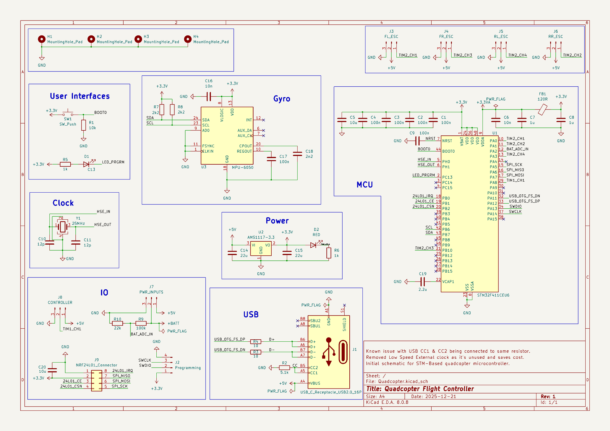
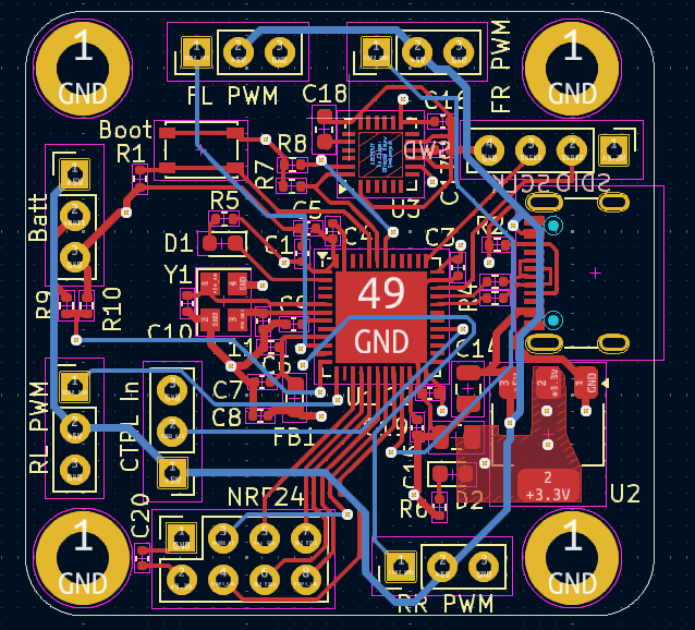
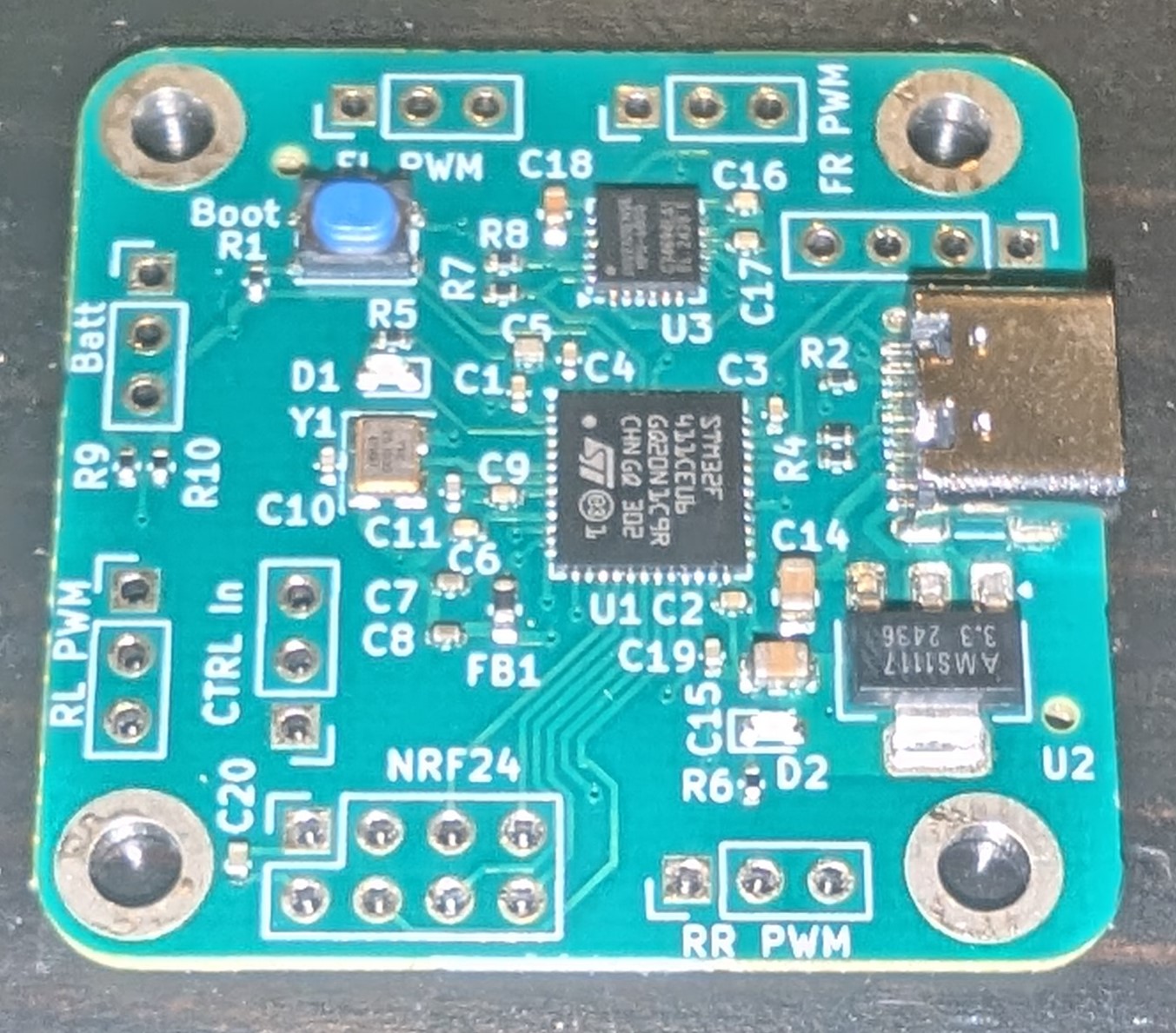
Below are images of the prototype perfboard wired up with the I2C (SDA=Yellow, SCL=White), PWM motor outputs (Green), PPM RC receiver input (Blue) and the battery ADC voltage divider across the resistors.


Final drone hardware with battery installed.


Created mount for MPU to reduce vibration impacting position accuracy.


| Qty | Value | Footprint | References |
|---|---|---|---|
| 6 | 100n | Capacitor_SMD:C_0402_1005Metric | C1, C2, C3, C4, C9, C17 |
| 4 | MountingHole_Pad | MountingHole:MountingHole_3.2mm_M3_DIN965_Pad | H1, H2, H3, H4 |
| 2 | 10 | Resistor_SMD:R_0402_1005Metric | R3, R4 |
| 2 | 10n | Capacitor_SMD:C_0402_1005Metric | C6, C16 |
| 2 | 10u | Capacitor_SMD:C_0402_1005Metric | C5, C20 |
| 2 | 12p | Capacitor_SMD:C_0402_1005Metric | C10, C11 |
| 2 | 1k | Resistor_SMD:R_0402_1005Metric | R5, R6 |
| 2 | 1u | Capacitor_SMD:C_0402_1005Metric | C7, C8 |
| 2 | 22u | Capacitor_SMD:C_0805_2012Metric | C14, C15 |
| 2 | 2k2 | Resistor_SMD:R_0402_1005Metric | R7, R8 |
| 1 | 100k | Resistor_SMD:R_0402_1005Metric | R9 |
| 1 | 10k | Resistor_SMD:R_0402_1005Metric | R1 |
| 1 | 120R | Inductor_SMD:L_0603_1608Metric | FB1 |
| 1 | 2.2u | Capacitor_SMD:C_0402_1005Metric | C19 |
| 1 | 22k | Resistor_SMD:R_0402_1005Metric | R10 |
| 1 | 25MHz | Crystal:Crystal_SMD_3225-4Pin_3.2x2.5mm | Y1 |
| 1 | 2n2 | Capacitor_SMD:C_0603_1608Metric | C18 |
| 1 | 5.1k | Resistor_SMD:R_0402_1005Metric | R2 |
| 1 | AMS1117-3.3 | Package_TO_SOT_SMD:SOT-223-3_TabPin2 | U2 |
| 1 | C13 | LED_SMD:LED_0603_1608Metric | D1 |
| 1 | CONTROLLER | Connector_PinHeader_2.54mm:PinHeader_1x03_P2.54mm_Vertical | J8 |
| 1 | FL_ESC | Connector_PinHeader_2.54mm:PinHeader_1x03_P2.54mm_Vertical | J3 |
| 1 | FR_ESC | Connector_PinHeader_2.54mm:PinHeader_1x03_P2.54mm_Vertical | J4 |
| 1 | MPU-6050 | Sensor_Motion:InvenSense_QFN-24_4x4mm_P0.5mm | U3 |
| 1 | NRF24L01_Connector | Connector_PinSocket_2.54mm:PinSocket_2x04_P2.54mm_Vertical | J9 |
| 1 | PWR_INPUTS | Connector_PinHeader_2.54mm:PinHeader_1x03_P2.54mm_Vertical | J7 |
| 1 | Programming | Connector_PinHeader_2.54mm:PinHeader_1x04_P2.54mm_Vertical | J2 |
| 1 | RED | LED_SMD:LED_0603_1608Metric | D2 |
| 1 | RL_ESC | Connector_PinHeader_2.54mm:PinHeader_1x03_P2.54mm_Vertical | J5 |
| 1 | RR_ESC | Connector_PinHeader_2.54mm:PinHeader_1x03_P2.54mm_Vertical | J6 |
| 1 | STM32F411CEU6 | Package_DFN_QFN:QFN-48-1EP_7x7mm_P0.5mm_EP5.6x5.6mm | U1 |
| 1 | SW_Push | Button_Switch_SMD:SW_SPST_PTS810 | SW1 |
| 1 | USB_C_Receptacle_USB2.0_16P | Connector_USB:USB_C_Receptacle_G-Switch_GT-USB-7010ASV | J1 |
pengshulin/mcush
MCUSH application platform (personal toolkit: firmware platform, debugger, hardware, test and application framework)

DsThakurRawat/PCB-AND-CHIP-DESIGN-WITH-AIML
All production files have been generated in manufacturing/: - Gerber Layers (RS-274X): Copper, solder masks, silkscreen, and board edge cuts (manufacturing/gerbers/) - Excellon Drill Files: Plated and non-plated drill…

heiso/macrolev
Macrolev is an open source analog keyboard powered by Hall Effect switches


It measures 38.5 × 37 mm and has 4 copper layers, 1.6 mm thick.
49 parts, built around the STM32F411CEU6, AMS1117-3.3, MPU-6050 and C13. The full list of its parts is on this page, with links to each part's symbol and footprint where PCBKit's library has them.
From the BenGrumm/STM-Quadcopter repository on GitHub, at the commit this page was made from: the board is PCB/Quadcopter/Quadcopter.kicad_pcb and its schematic PCB/Quadcopter/Quadcopter.kicad_sch. PCBKit opens the board in the browser, with nothing to install.
Its repository states no licence, so its author keeps all rights: ask BenGrumm before reusing the design.