2 layers148.6 × 192.2 mm
Badge
NuttyShell/NuttyBadge
NuttyBadge: A NuttyShell crafted multi-tool. Opensourced Hardawre and Software
169 parts31GPL-3.0
 bendixsonnenberg/watering_controller1
Codewise: an exploration of using embedded rust, specificaly embassy.
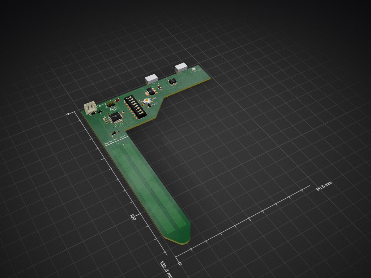
Moisture sensor is an open-source printed circuit board by bendixsonnenberg, from the bendixsonnenberg/watering_controller repository on GitHub, published under the MIT licence. It is a 2-layer board of 96.5 × 132.4 mm with 30 parts on 55 nets, routed with 424 tracks and 57 vias.
It is built around the MCP2551-I/SN-HG, AMS1117-3.3 and 1N4148W, with the AO3400A and WS2812B among its other parts. Its parts include 12 capacitors, 4 connectors, 3 resistors, 3 ICs and 3 diodes. It belongs with the sensors and measurement boards and the STM32 boards of this library.


A tinkering project to automate watering plants in a greenhouse and analyzing data afterwards.
Current Progress can be seen in "Status" at the bottom.
Codewise: an exploration of using embedded rust, specificaly embassy.
Per pot:
Central Controller:
Additional Hardware needed:
The central controller communicates with each moisture sensor over CAN-Bus. The Specs for this Communication can be found here. The implementation is found here. The moisture sensors get a threshold and use their valves to hold that threshold, currently through a simple comparision (potential PID).
August '25: Web-functions added, central controller accesses WLAN. Sensorreadings possible through network with webinterface-prototype.
After building a greenhouse on our little roof terrace for my fiancée, I stumbled upon the biggest problem in the private greenhouse industry. While tomatoes and cucumbers thrived, the biggest recurring problem was watering the plants, as you have to do so every day; on hot days, multiple times a day.
The solution was obvious: I turned to my good friend Bendix and we started engineering the hell out of this seemingly small problem. The idea got bigger and bigger, until we suddenly had the first prototype running on a cheap patch panel. Our system was actually
reading live moisture data and maintaining a moisture level for several days. The next step was soldering prototype v2, which is currently running in the greenhouse.
Throughout the process, I had lots of ideas for little extras, such as a menu operated through a rotary encoder on an LCD display or RGB LEDs. Because everything is better with RGB. The final version is supposed to support up to 256 pots (far too many for the 2 x 1.2m²), so the system is adaptable for larger greenhouses. We are planning to implement a
web interface and push notifications to smartphones, so even while being abroad, there is no need for close monitoring by a third party. But these are future dreams. Our current priority is the watering and monitoring functionality – all while the CAN network does its job.
Bendix has been documenting his progress in code here since day one. I joined GitHub mainly to be a part of it. To be honest: I have absolutely no clue about coding other than basic principles and a rough idea of what computers can do. My main background is being a mechanic by trade. Now I do my part by
trying to document our progress and give a little context about what we do.
I'll try to update regularly – who knows, this might one day attract public interest.
Small Addition: I startet building a webinterface, all while learning how to work with HTML and JavaScript. If you're interested, click here.
-Philipp
June '25: working menu on LCD-Display with individual IDs and live data, navigation possible through rotary encoder and "return"-button
June '25: data saved, showing 9 day continuous watering without crashes or similar issues; moisture level plausible
July '25: Hardware for easier refilling added, also new water container
July '25: Webinterface concept working, reference here.
August '25: Access to live data possible through Webinterface concept.
Up to July '25: Two pot-sensors together with central controller, currently set up in greenhouse, with CAN-Network and watering function working as far as assessable. Menu working, displayed on LCD.
Up to August '25: Three pot-sensors together with central controller, currently set up in greenhouse, with CAN-Network and watering function working fairly reliable. Menu working, displayed on LCD. RGB-LEDs added for easier identification while changing thresholds. Humidity/Temperaturesensor added. All data is logged on SD-Card.
| Qty | Value | Footprint | References |
|---|---|---|---|
| 6 | 100n | PCM_JLCPCB:C_0402 | C1, C2, C3, C5, C6, C9 |
| 3 | 10k | PCM_JLCPCB:R_0402 | R1, R2, R3 |
| 2 | 1N4148W | PCM_JLCPCB:D_SOD-123 | D1, D2 |
| 2 | 1u | PCM_JLCPCB:C_0603 | C7, C8 |
| 2 | 22u | Capacitor_SMD:C_1206_3216Metric | C10, C11 |
| 2 | USB_C_Plug_USB2.0 | Connector_USB:USB_C_Plug_JAE_DX07P024AJ1 | P1, P2 |
| 1 | 100n | Capacitor_SMD:C_0402_1005Metric | C14 |
| 1 | 10u | PCM_JLCPCB:C_0603 | C4 |
| 1 | 120R | PCM_JLCPCB:L_0603 | FB1 |
| 1 | AMS1117-3.3 | Package_TO_SOT_SMD:SOT-223-3_TabPin2 | U3 |
| 1 | AO3400A | PCM_JLCPCB:Q_SOT-23 | Q1 |
| 1 | Conn_01x02_Pin | Connector_JST:JST_EH_B2B-EH-A_1x02_P2.50mm_Vertical | J2 |
| 1 | Conn_01x04_Socket | Connector_PinHeader_1.27mm:PinHeader_1x04_P1.27mm_Vertical | J1 |
| 1 | MCP2551-I-SN | Package_SO:SOIC-8_3.9x4.9mm_P1.27mm | U2 |
| 1 | STM32F103C8Tx | Package_QFP:LQFP-48_7x7mm_P0.5mm | U1 |
| 1 | SW_DIP_x08 | Button_Switch_SMD:SW_DIP_SPSTx08_Slide_6.7x21.88mm_W6.73mm_P2.54mm_LowProfile_JPin | SW3 |
| 1 | SW_SPDT | PCM_JLCPCB:SOT-23-3_L2.9-W1.3-P0.95-LS2.4-BR | SW2 |
| 1 | Tactile Button, 160gf | PCM_JLCPCB:SW-SMD_4P-L5.1-W5.1-P3.70-LS6.5-TL-2 | S1 |
| 1 | WS2812B | LED_SMD:LED_WS2812B-2020_PLCC4_2.0x2.0mm | D3 |
It measures 96.5 × 132.4 mm and has 2 copper layers, 1.6 mm thick.
30 parts, built around the MCP2551-I/SN-HG, AMS1117-3.3, 1N4148W and AO3400A. The full list of its parts is on this page, with links to each part's symbol and footprint where PCBKit's library has them.
From the bendixsonnenberg/watering_controller repository on GitHub, at the commit this page was made from: the board is hardware/sensor/moisture_sensor/moisture_sensor.kicad_pcb and its schematic hardware/prototypes/sensor/Moisturesensor.kicad_sch. PCBKit opens the board in the browser, with nothing to install.
Its repository publishes it under the MIT licence: you may reuse it on that licence's terms (keep the author's notice, and for a copyleft licence share your changes alike).
NuttyShell/NuttyBadge
NuttyBadge: A NuttyShell crafted multi-tool. Opensourced Hardawre and Software


Robast-GmbH/PCB_Designs
This repository contains all the necessary files and instructions for the PCBs that are designed using KiCad. Here is an overview of the main components: - .github: Contains Github-specific configurations, including…

Nomalah/Budget-Racing-Electronics
All electronics for the budget racing vehicle

jadenrhee/wigglecam-controller
RP2040 co-processor board for a 4-lens wigglegram camera: constant-current flash, controls, battery telemetry, Pi 5 I2C interface. 4-layer, DRC-clean, fab-ready.


0xjmux/iot_leddriver_hw
ESP32-based WS2812B LED Strip Driver PCB, designed for music visualization
