
4 layers127.4 × 141.4 mm
Authenticator2.0
Hypernova-Oy/emb-toveri
Weatherproof embedded user authenticator and authorizator device
54 partsGPL-3.0
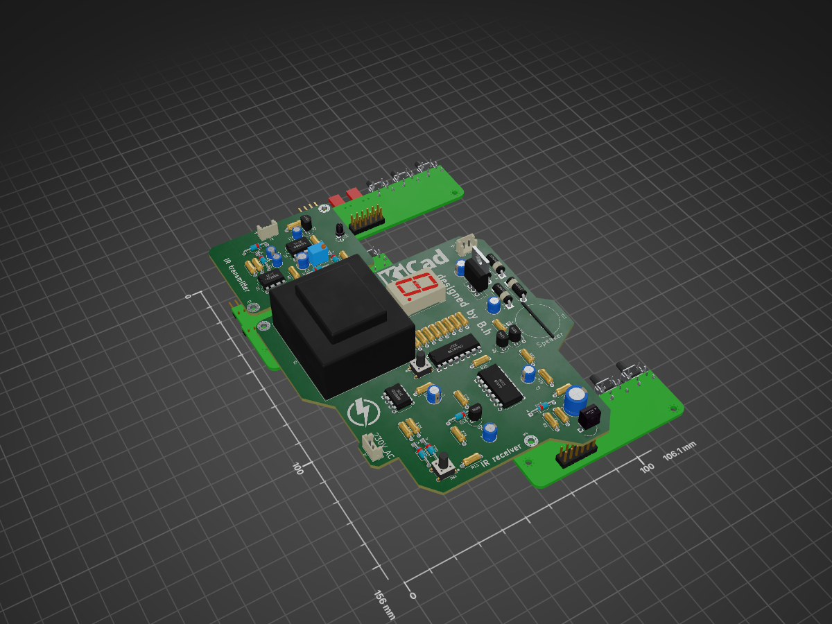
This project is a complete PCB-based system that detects interruptions between an IR emitter and receiver. When an object blocks the IR beam: - A buzzer/speaker is triggered, - A 7-segment display counter is…
Essaie is an open-source printed circuit board by bejaouihamza, from the bejaouihamza/https-github.com-bejaouihamza-IR-Interruption-Detector repository on GitHub. It is a 2-layer board of 106 × 156 mm with 77 parts on 67 nets, routed with 627 tracks and 0 vias.
It is built around the NE555D, CD4033BE and L7812, with the 1N4148WT, AST-1732MR-R and BZV55B3V3 among its other parts. Its parts include 27 resistors, 14 diodes, 10 capacitors, 8 ICs and 4 transistors.


This project is a complete PCB-based system that detects interruptions between an IR emitter and receiver. When an object blocks the IR beam:
The circuit is entirely based on discrete components, including NE555 timers, CD40106, and a CD4033 counter/decoder. It also includes a robust regulated power supply, and can be used in security, object-counting, or automation systems.


The power input is 230V AC, stepped down using a transformer and rectified via a bridge diode. The output is regulated to +12V DC using a 7812 voltage regulator.
| Component | Quantity | Notes |
|---|---|---|
| NE555 | 3 | Signal modulation and detection |
| TSOP2254 | 1 | IR receiver |
| TSAL4400 | 1 | IR LED |
| CD40106 | 1 | Schmitt trigger inverter |
| CD4033B | 1 | BCD Counter |
| D168K | 1 | 7-Segment Display |
| AST-1732MR-R | 1 | Buzzer/Speaker |
| Q1, Q2, Q3 | 3 | NPN transistors |
| TP4056 | 1 (opt.) | Optional for battery version |
| AMS1117-3.3 | 1 (opt.) | Optional for low-voltage designs |
Designed by Bejaoui Hamza
Date: 18 June 2025
Project name: IR Interruption Detector
This project is open-source under the MIT License.
| Qty | Value | Footprint | References |
|---|---|---|---|
| 7 | R | Resistor_THT:R_Axial_DIN0207_L6.3mm_D2.5mm_P7.62mm_Horizontal | R14, R15, R16, R17, R18, R19, R20 |
| 5 | 1KR | Resistor_THT:R_Axial_DIN0207_L6.3mm_D2.5mm_P7.62mm_Horizontal | R3, R4, R23, R26, R27 |
| 4 | 1N4148WT | Diode_THT:D_5W_P10.16mm_Horizontal | D1, D2, D3, D4 |
| 4 | D | Diode_THT:D_DO-35_SOD27_P10.16mm_Horizontal | D6, D7, D8, D9 |
| 4 | MountingHole | MountingHole:MountingHole_2.5mm_Pad_Via | H1, H2, H3, H4 |
| 4 | NPN | Package_TO_SOT_THT:TO-92_Inline | Q1, Q2, Q3, Q4 |
| 3 | 100R | Resistor_THT:R_Axial_DIN0207_L6.3mm_D2.5mm_P7.62mm_Horizontal | R1, R12, R13 |
| 3 | 10KR | Resistor_THT:R_Axial_DIN0207_L6.3mm_D2.5mm_P7.62mm_Horizontal | R11, R21, R25 |
| 3 | Conn_01x02_Pin | Connector_JST:JST_EH_B2B-EH-A_1x02_P2.50mm_Vertical | J1, J2, J3 |
| 3 | NE555D | Package_DIP:DIP-8_W7.62mm | U2, U3, U6 |
| 2 | 0.01u | Capacitor_THT:CP_Radial_D4.0mm_P1.50mm | C6, C11 |
| 2 | 100KR | Resistor_THT:R_Axial_DIN0207_L6.3mm_D2.5mm_P7.62mm_Horizontal | R22, R24 |
| 2 | 19.6kR | Resistor_THT:R_Axial_DIN0207_L6.3mm_D2.5mm_P7.62mm_Horizontal | R5, R6 |
| 2 | 1N4148WT | Diode_THT:D_DO-35_SOD27_P10.16mm_Horizontal | D13, D14 |
| 2 | LOGO | LOGO | G***, G*** |
| 2 | SW_Push_Dual_x2 | footprints:SW_FSM8JH | SW1, SW2 |
| 1 | 0.1uf | Capacitor_THT:CP_Radial_D5.0mm_P2.50mm | C2 |
| 1 | 0.33uf | Capacitor_THT:CP_Radial_D5.0mm_P2.50mm | C1 |
| 1 | 100KR | Potentiometer_THT:Potentiometer_Bourns_3266W_Vertical | RV1 |
| 1 | 100nF | Capacitor_THT:CP_Radial_D5.0mm_P2.50mm | C3 |
| 1 | 100nf | Capacitor_THT:CP_Radial_D5.0mm_P2.50mm | C7 |
| 1 | 1nF | Capacitor_THT:CP_Radial_D4.0mm_P1.50mm | C4 |
| 1 | 1nf | Capacitor_THT:CP_Radial_D5.0mm_P2.50mm | C9 |
| 1 | 1uf | Capacitor_THT:CP_Radial_D5.0mm_P2.50mm | C8 |
| 1 | 4.7KR | Resistor_THT:R_Axial_DIN0207_L6.3mm_D2.5mm_P7.62mm_Horizontal | R9 |
| 1 | 40106 | Package_DIP:DIP-14_W10.16mm | U10 |
| 1 | 47KR | Resistor_THT:R_Axial_DIN0207_L6.3mm_D2.5mm_P7.62mm_Horizontal | R8 |
| 1 | 47R | Resistor_THT:R_Axial_DIN0207_L6.3mm_D2.5mm_P7.62mm_Horizontal | R7 |
| 1 | 47uf | Capacitor_THT:CP_Radial_D8.0mm_P3.50mm | C5 |
| 1 | 4KR | Resistor_THT:R_Axial_DIN0207_L6.3mm_D2.5mm_P7.62mm_Horizontal | R10 |
| 1 | 8KR | Resistor_THT:R_Axial_DIN0207_L6.3mm_D2.5mm_P7.62mm_Horizontal | R2 |
| 1 | AST-1732MR-R | footprints:SPKR_AST-1732MR-R | LS1 |
| 1 | BZV55B3V3 | Diode_THT:D_DO-35_SOD27_P10.16mm_Horizontal | D12 |
| 1 | BZV55B3V9 | Diode_THT:D_DO-35_SOD27_P10.16mm_Horizontal | D11 |
| 1 | BZV55B5V1 | Diode_THT:D_DO-35_SOD27_P10.16mm_Horizontal | D10 |
| 1 | CD4033B | Package_DIP:DIP-16_W7.62mm | U7 |
| 1 | D168K | Display_7Segment:D1X8K | U8 |
| 1 | L7812 | Package_TO_SOT_THT:TO-220-3_Vertical | U1 |
| 1 | TSAL4400 | LED_THT:LED_D3.0mm_IRBlack | D5 |
| 1 | TSOP32S40F | OptoDevice:Vishay_MOLD-3Pin | U14 |
| 1 | Transformer_1P_1S | Transformer_THT:Transformer_37x44 | T1 |
It measures 106 × 156 mm and has 2 copper layers, 1.6 mm thick.
77 parts, built around the NE555D, CD4033BE, L7812 and 1N4148WT. The full list of its parts is on this page, with links to each part's symbol and footprint where PCBKit's library has them.
From the bejaouihamza/https-github.com-bejaouihamza-IR-Interruption-Detector repository on GitHub, at the commit this page was made from: the board is essaie.kicad_pcb and its schematic essaie.kicad_sch. PCBKit opens the board in the browser, with nothing to install.
Its repository states no licence, so its author keeps all rights: ask bejaouihamza before reusing the design.
Hypernova-Oy/emb-toveri
Weatherproof embedded user authenticator and authorizator device

TheTesla/lightbarriersync
Robust light barrier with snychronized carrierer wave receiver

Genexiz/Seven_Segment_Counter
This project is part of From Schematic to PCB: Layout Fundamentals Course


muhammadsyafrieagunghandaya-dotcom/MyPCB
This repository contains my collection of PCB design works created using KiCad and other tools. Most of these projects are part of my learning process in electronics, along with some experiments and personal ideas.


Sakib-Ansari/Linear_Programmable_Power_Supply
This repository contains the complete KiCad project for a multi-board linear programmable bench power supply. The design is organized into separate PCBs, including the Power Board, Control Board, Front Panel, Output…

Bulldozeru/Hardware-and-Electronics
This is a repository where I add my PCB and Electronics Design