2 layers78 × 55 mm
Emtpy boomerang shield template
bazsimarkus/avr-basic-sbc
An ATmega1284P-based single board computer with composite video output, PS/2 keyboard input, running Tiny BASIC.
11 parts
 bazsimarkus/avr-basic-sbc
An ATmega1284P-based single board computer with composite video output, PS/2 keyboard input, running Tiny BASIC.
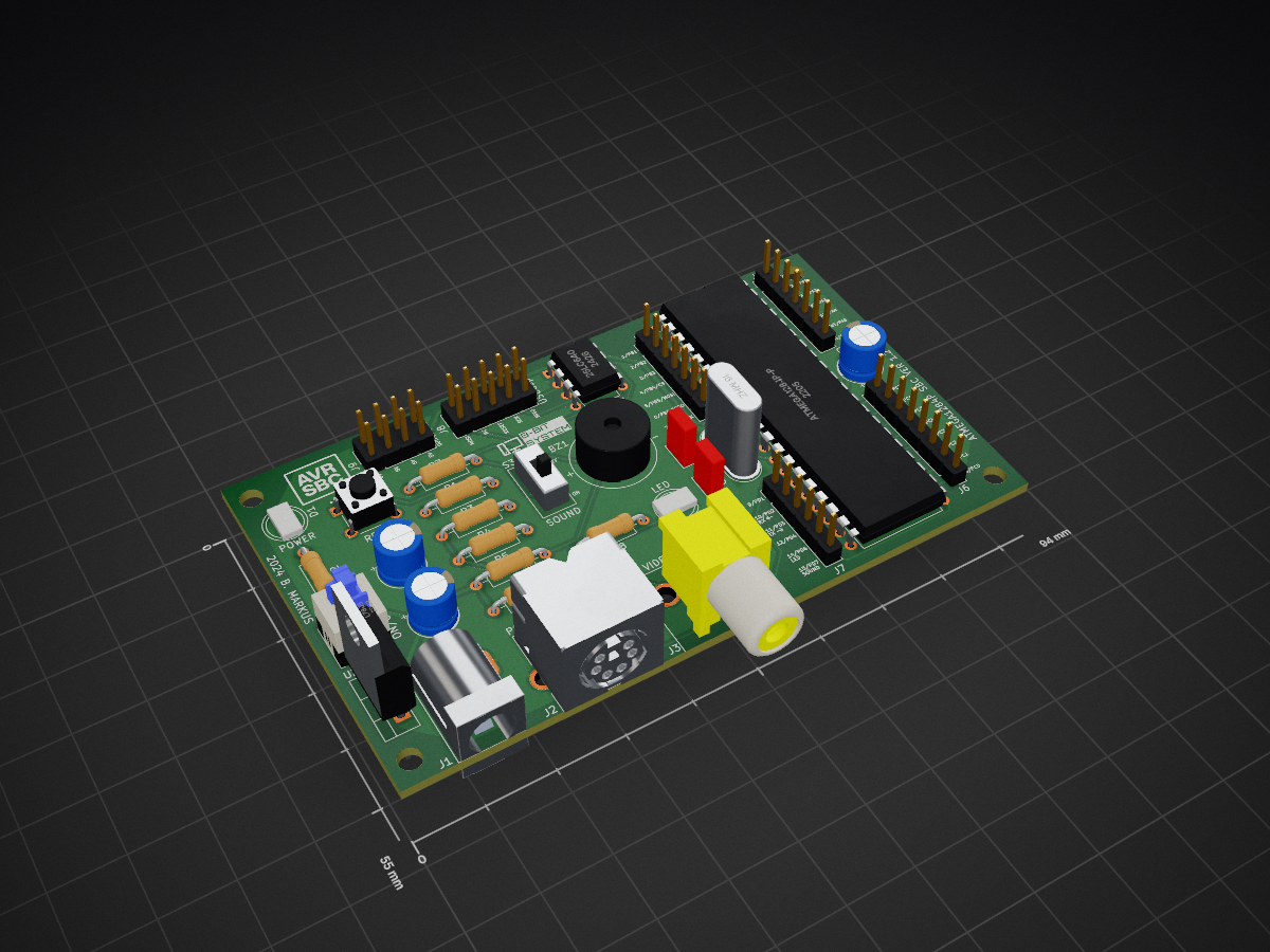
Avr basic sbc is an open-source printed circuit board by bazsimarkus, from the bazsimarkus/avr-basic-sbc repository on GitHub. It is a 2-layer board of 94 × 55 mm with 38 parts on 58 nets, routed with 205 tracks and 0 vias.
It is built around the ATMEGA1284P-PU, 25LC640-E/P and L7805. Its parts include 9 connectors, 8 resistors, 5 capacitors, 3 ICs and 3 switches. It belongs with the computers and single-board computers and keyboards and input boards and the AVR (ATmega, ATtiny) boards of this library.


An ATmega1284P-based single board computer
Composite video output • PS/2 keyboard input • Tiny BASIC interpreter with graphics, sound, GPIO, and serial I/O
|
|
I always loved retrocomputing. As a kid I played around with a Commodore 64 - which I still own to this day - and I was always fascinated by the fact that computers are really just embedded systems, just nowadays unimaginably fast ones. This project grew out of that fascination.
The idea is not completely original. Many people have built similar things, and my two biggest inspirations were Jörg Wolfram's AVR ChipBASIC and Juan J. Martínez's DAN64. Neither was quite what I had in mind though - I wanted something simple to use, simple to develop for, and simple to build. A Tiny BASIC based single board computer with composite video output, a PS/2 keyboard, and some GPIO, all on a single through-hole PCB. So I decided to build my own, and here it is.
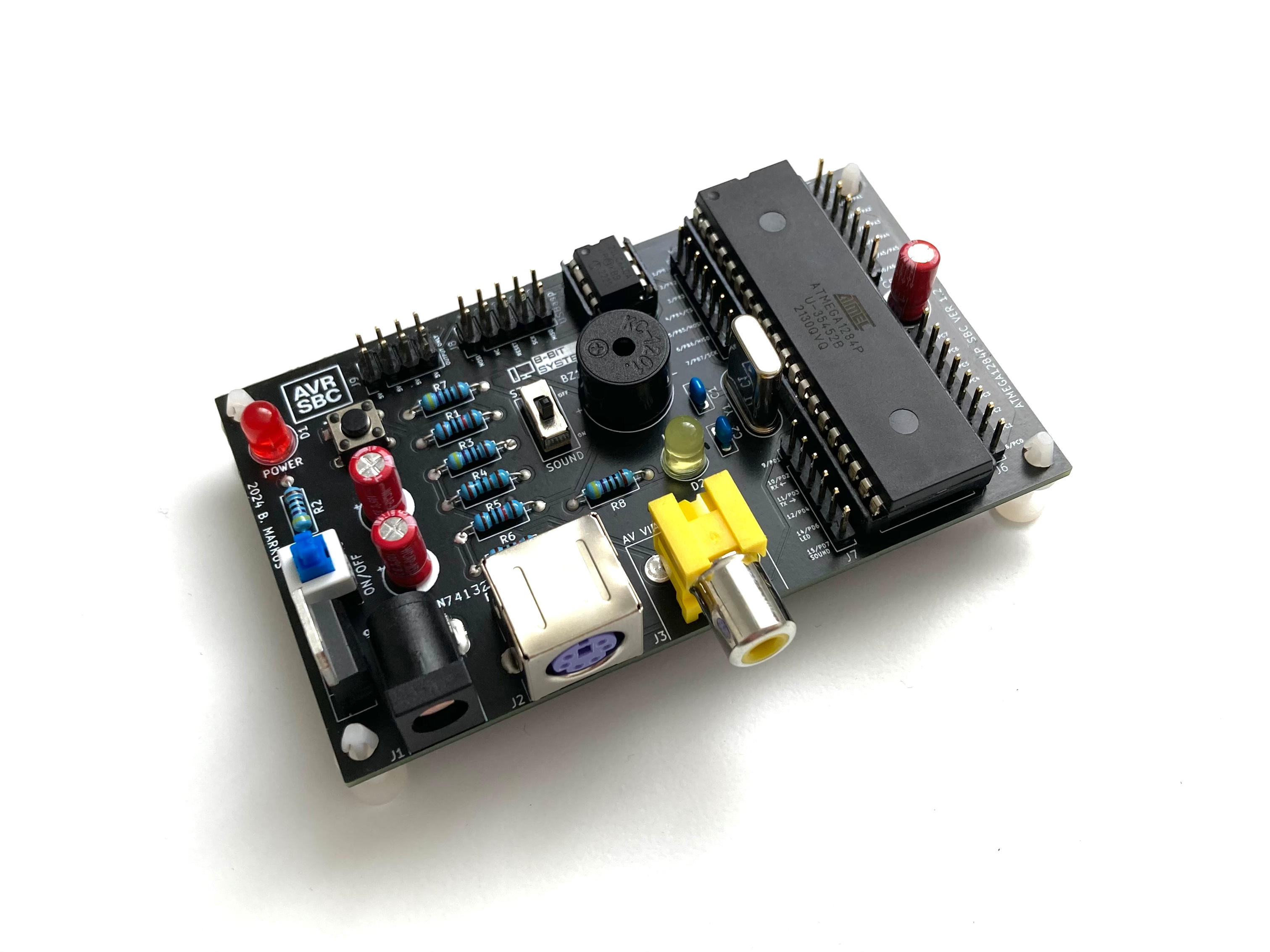
The AVR-SBC is an ATmega1284P-based single board computer running a Tiny BASIC interpreter. It generates a composite video signal (320×240, PAL) directly from the microcontroller, accepts input from a PS/2 keyboard, has an onboard buzzer for sound, and exposes GPIO pins for interacting with the outside world. There is also an external 25LC640 SPI EEPROM for storing programs and data - I particularly like using it to store bitmaps that can be drawn on the screen. The internal EEPROM of the ATmega1284P is available too, so a typical setup is storing a drawing program in the internal EEPROM and the actual bitmap data in the external one.
The whole thing is built with plain avr-gcc and avrdude. No Arduino framework, no dependencies - just good old C and a bit of assembly where the timing gets tight.
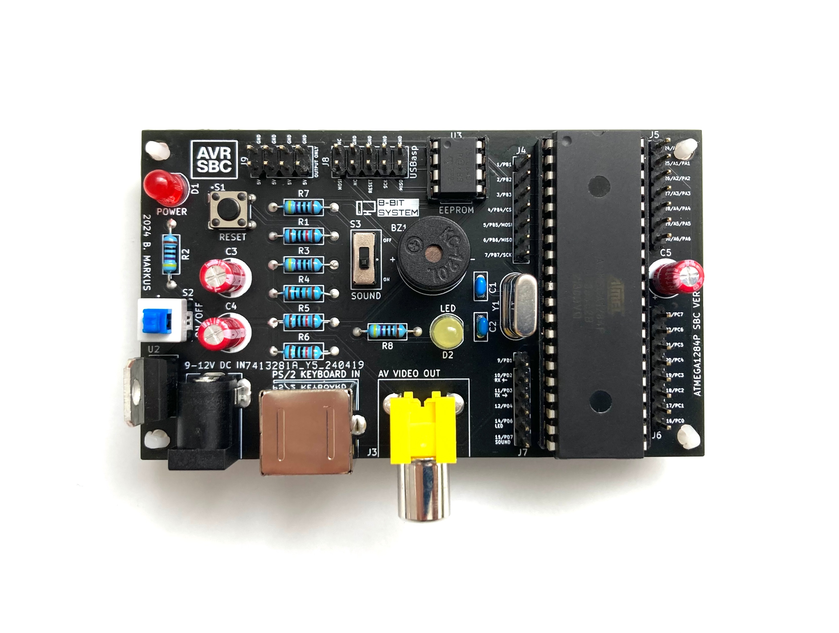
TONE, TONEW, NOTONE commands for playing melodies, with a slide switch to disable itXPOKE, XPEEK, XSAVE, XLOAD, XFORMAT; great for storing bitmapsEPOKE, EPEEK, ESAVE, ELOAD, EFORMATDWRITE, DREAD, AWRITE, AREAD commands using MightyCore-style pin numberingSERLOADavr-gcc and avrdudeThe AVR-SBC is a fully through-hole PCB, which was a deliberate choice - it makes it easy to solder by hand and easy to modify. The board is revision v1.2. Versions v1.0 and v1.1 were non-working prototypes that got soldered, debugged, and eventually thrown away. The third one worked, and it has been working reliably ever since.
The heart of the board is the ATmega1284P in a DIP-40 socket, running off a 16 MHz HC49-U crystal. Power comes in through a standard 2.1mm DC barrel jack and is regulated to 5V by an L7805CV linear regulator. There are two LEDs - a red power indicator and a yellow user-controllable one on PD6. A tactile button handles reset, a toggle switch controls power, and a slide switch can disconnect the buzzer if you get tired of the beeping.
Video goes out through an RCA jack. The PS/2 keyboard connector is a right-angle Mini-DIN. There is also an external 25LC640 SPI EEPROM in a DIP-8 socket, and a 2×5 USBasp ISP programming header.
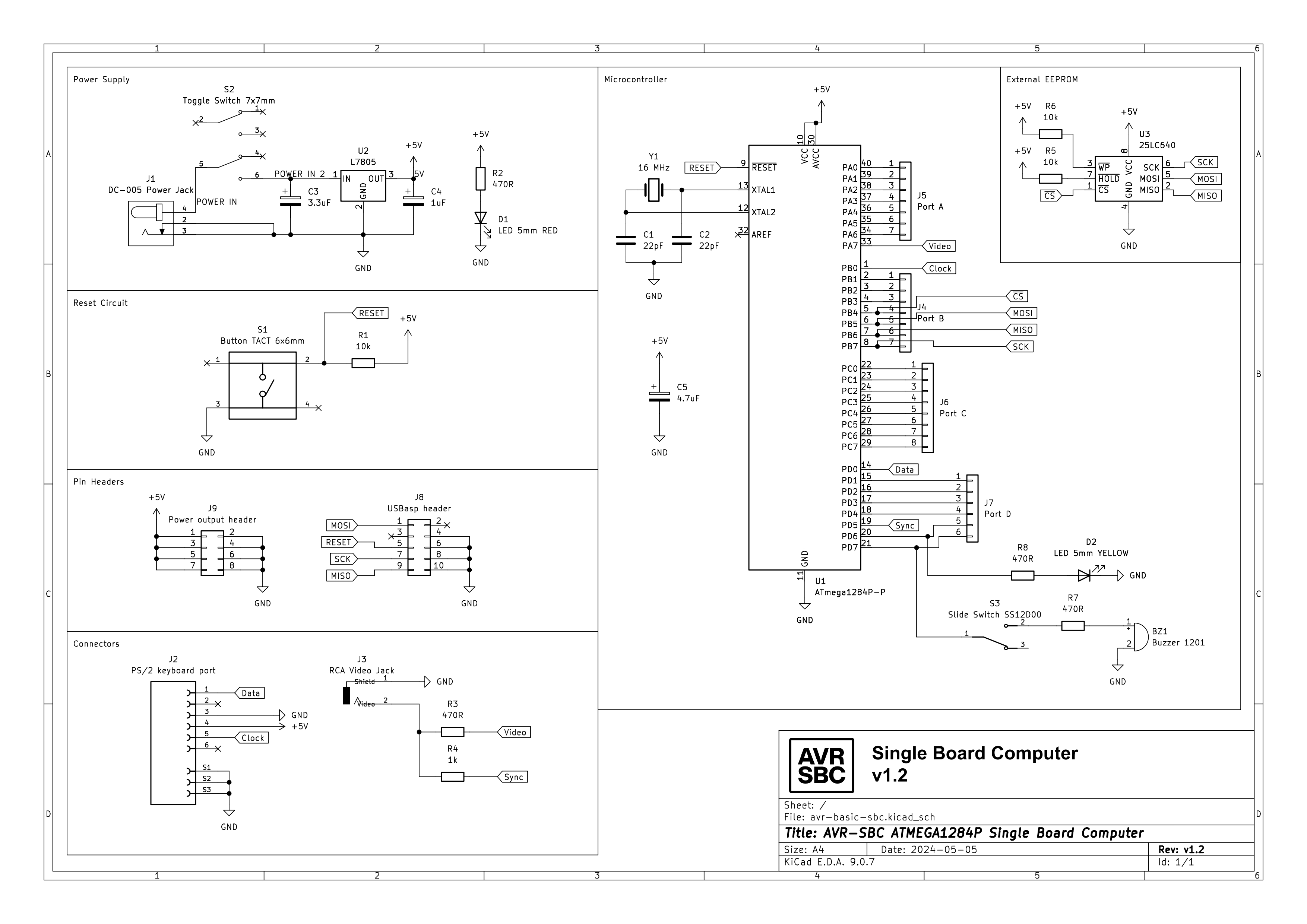
The full KiCad project including schematic, PCB, and Gerber files is available in the schematic/ folder.
| Reference | Qty | Value / Part |
|---|---|---|
| U1 | 1 | ATmega1284P-P (DIP-40) |
| U2 | 1 | L7805CV - 5V linear regulator (TO-220) |
| U3 | 1 | 25LC640 - SPI EEPROM 8KB (DIP-8) |
| Y1 | 1 | 16 MHz crystal (HC49-U) |
| BZ1 | 1 | Buzzer (polarized, 1201 footprint) |
| C1, C2 | 2 | 22 pF - crystal load capacitors |
| C3 | 1 | 3.3 µF electrolytic |
| C4 | 1 | 1 µF electrolytic |
| C5 | 1 | 4.7 µF electrolytic |
| D1 | 1 | LED 5mm RED - power indicator |
| D2 | 1 | LED 5mm YELLOW - user LED (PD6) |
| R1, R5, R6 | 3 | 10 kΩ |
| R2, R3, R7, R8 | 4 | 470 Ω |
| R4 | 1 | 1 kΩ |
| S1 | 1 | Tactile button 6×6mm - reset |
| S2 | 1 | Toggle switch 7×7mm - power |
| S3 | 1 | Slide switch - buzzer on/off |
| J1 | 1 | DC barrel jack 2.1mm (DC-005) |
| J2 | 1 | PS/2 keyboard connector (Mini-DIN 6) |
| J3 | 1 | RCA video jack |
| J4-J7 | 4 | Pin headers - Port B, A, C, D GPIO |
| J8 | 1 | 2×5 pin header - USBasp ISP |
| J9 | 1 | 2×4 pin header - power output |
The firmware uses MightyCore-style pin numbering for the ATmega1284P, which is also what the BASIC DWRITE, DREAD, AWRITE, and AREAD commands expect.
| Pin | Port | Function | Available? |
|---|---|---|---|
| 0 | PB0 | PS/2 keyboard clock | ✗ reserved |
| 1-3 | PB1-PB3 | GPIO (J4) | ✓ |
| 4-7 | PB4-PB7 | SPI - EEPROM /CS, MOSI, MISO, SCK | shared |
| 8 | PD0 | PS/2 keyboard data | ✗ reserved |
| 9 | PD1 | UART1 TX | ✓ |
| 10 | PD2 | UART1 RX | ✓ |
| 11-12 | PD3-PD4 | GPIO (J7) | ✓ |
| 13 | PD5 | Video sync output | ✗ reserved |
| 14 | PD6 | Yellow LED | ✓ |
| 15 | PD7 | Buzzer / OC2A | ✓ |
| 16-23 | PC0-PC7 | GPIO (J6) - fully free | ✓ |
| 24-30 | PA0-PA6 | GPIO (J5) - exposed on header, but see note | ⚠ see note |
| 31 | PA7 | Video data output | ✗ reserved |
Note on PORTA: The high-resolution line rendering routine writes pixel data to the entire PORTA register using the AVR
OUTinstruction (1 cycle, cycle-exact timing). This means the whole port is effectively owned by the video system at runtime. The pins are physically accessible on the J5 header, but using them as GPIO will corrupt the video output. PORTC is the recommended alternative for free GPIO pins.
The firmware is pure C (and one assembly file), built with avr-gcc and flashed with avrdude. No Arduino framework, no HAL, no magic. Everything is wired up by hand.
The three hardware timers are each assigned a dedicated role and they all have to coexist without stepping on each other, which was honestly one of the trickier parts of getting this running:
| Timer | Role |
|---|---|
| Timer0 | 1 ms system tick (CTC mode) - used by DELAY and the tone duration counter |
| Timer1 | Composite video sync and scanline generation |
| Timer2 | Tone output on OC2A / PD7 - drives the buzzer via TONE / TONEW |
Memory is tight. The ATmega1284P has 16 KB of SRAM, and between the 9600-byte framebuffer (320×240 ÷ 8) and the 5500-byte BASIC program buffer, there is not much room left. It works, but there is not a lot of headroom to play with.
The video output is the part I am most proud of - and the part that gave me the most trouble.
I originally used the Arduino TVout library like most similar projects do. It works, but the resolution is limited and I never really liked how it looked. I wanted 320×240, so I decided to write my own graphics library. That turned out to be a good decision, but it had consequences.
The line rendering function - render_scanline() in render_line.S - has to output one pixel every single clock cycle to hit 320 pixels per line at 16 MHz. There is simply no way to do that in C. Even a tight loop has overhead that breaks the timing. So I wrote it in AVR assembly, fully unrolled, 40 bytes × 8 bits per byte, outputting each pixel with a single OUT instruction directly to PORTA. No loop, no branches, just 320 consecutive OUT and LSL pairs.
The downside is that OUT writes to the entire port at once. That means PORTA is permanently reserved by the video system at runtime - the pins are physically on the J5 header, but you cannot use them as GPIO without corrupting the video output. PORTC has 8 fully free pins (J6) and is the recommended alternative. I never found a way around this limitation at 320×240, so I left it as-is. Ideas are welcome.
The graphics library (graphics.c) supports:
SET, CLEAR, XORThe text terminal layer (text.c) sits on top of the graphics library and provides a 40×30 character terminal with scrolling, wrap-around, and a blinking cursor.
The firmware is almost a direct port of TinyBASIC, originally written by Gordon Brandly as 68000 Tiny Basic, then ported to C by Michael Field as Arduino Basic, and further developed by Scott Lawrence as TinyBasicPlus. I adapted it to be fully AVR C based - no Arduino framework anywhere.
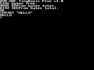
On startup, the board displays a splash screen with the firmware version and available memory, then drops into the interactive > prompt.
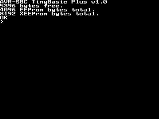
The BASIC command set includes everything you would expect, plus a bunch of hardware-specific extensions:
| Command | Description | Example |
|---|---|---|
PRINT expr, expr, ... | Prints expressions (strings or numbers) to the screen. Items separated by ,. End with ; to suppress newline. ? is a shorthand alias. | PRINT "HELLO", X |
INPUT var | Prompts the user with ? and reads a numeric value into variable var (A-Z). | INPUT A |
LET var = expr | Assigns the value of an expression to a variable (A-Z). The LET keyword is optional. | LET X = 42 or X = 42 |
IF expr THEN statement | Evaluates expression; if non-zero, executes the statement after THEN. THEN is optional. Relational operators: =, <>, !=, <, >, <=, >=. | IF X > 10 THEN PRINT "BIG" |
GOTO expr | Jumps to the line number given by the expression. | GOTO 100 |
GOSUB expr | Calls the subroutine at the given line number, pushing a return address onto the stack. | GOSUB 500 |
RETURN | Returns from the most recent GOSUB call. | RETURN |
FOR var = expr TO expr [STEP expr] | Begins a counting loop. Variable iterates from start to end value. STEP defaults to 1 if omitted. | FOR I = 1 TO 10 STEP 2 |
NEXT var | Advances the FOR loop variable and branches back if the loop has not finished. | NEXT I |
END | Stops program execution and returns to the prompt. | END |
STOP | Same as END - stops program execution. | STOP |
REM text | Comment line; everything after REM (or ') is ignored. | REM THIS IS A COMMENT |
| Command | Description | Example |
|---|---|---|
RUN | Executes the stored program from the first line. | RUN |
LIST [linenum] | Lists the stored program. If a line number is given, listing starts from that line. | LIST or LIST 100 |
NEW | Erases the stored program from memory. | NEW |
LOAD | Loads a program (stub - unimplemented on this platform). | LOAD |
SAVE | Saves a program (stub - unimplemented on this platform). | SAVE |
CHAIN | Loads a program and auto-runs it after loading (stub - unimplemented on this platform). | CHAIN |
MEM | Prints the number of free BASIC program bytes and EEPROM usage statistics. | MEM |
BYE | Exits the BASIC interpreter. | BYE |
| Command | Description | Example |
|---|---|---|
DWRITE pin, value | Sets a digital GPIO pin HIGH or LOW. Value can be HIGH/HI, LOW/LO, or a numeric expression (0/1). Uses MightyCore pin numbering. | DWRITE 14, 1 |
AWRITE pin, value | Writes an analog (PWM) value to a GPIO pin. Same syntax as DWRITE. | AWRITE 14, 128 |
DREAD(pin) | Function - reads a digital pin and returns 1 (HIGH) or 0 (LOW). Enables the internal pull-up resistor. | X = DREAD(16) |
AREAD(pin) | Function - reads an analog value (0-1023) from an ADC pin (pins 24-30 only). | X = AREAD(24) |
| Command | Description | Example |
|---|---|---|
DRAWPIX x, y, c | Draws a single pixel at (x, y) with draw mode c (0=clear, 1=set, 2=xor). | DRAWPIX 160, 120, 1 |
DRAWLINE x0, y0, x1, y1, c | Draws a line from (x0, y0) to (x1, y1) with draw mode c. | DRAWLINE 0, 0, 319, 239, 1 |
DRAWRECT x, y, w, h, c, f | Draws a rectangle at (x, y) with width w and height h. Outline uses draw mode c, fill uses draw mode f. Use -1 for f to draw outline only. | DRAWRECT 10, 10, 50, 30, 1, 1 |
DRAWCIRC cx, cy, r, c, f | Draws a circle centered at (cx, cy) with radius r. Outline uses draw mode c, fill uses draw mode f. Use -1 for f to draw outline only. | DRAWCIRC 160, 120, 40, 1, 0 |
DRAWCHAR x, y, char | Draws a single 8×8 character at pixel position (x, y). The character is the literal next character in the source. | DRAWCHAR 10, 10, A |
GETPIX x, y | Prints the pixel value (0 or 1) at position (x, y) to the screen. | GETPIX 100, 50 |
CLS | Clears the entire screen and resets the text cursor. | CLS |
| Command | Description | Example |
|---|---|---|
TONE freq, duration | Starts playing a tone at freq Hz for duration ms on the buzzer. Execution continues immediately. | TONE 440, 500 |
TONEW freq, duration | Plays a tone at freq Hz for duration ms and waits until the tone finishes before continuing. | TONEW 440, 500 |
NOTONE | Immediately stops any tone currently playing. | NOTONE |
| Command | Description | Example |
|---|---|---|
DELAY expr | Pauses execution for the given number of milliseconds. Breakable with ESC or Ctrl-C. | DELAY 1000 |
| Command | Description | Example |
|---|---|---|
ESAVE | Saves the current program to internal EEPROM. | ESAVE |
ELOAD | Loads a program from internal EEPROM into RAM. | ELOAD |
ELIST | Lists the contents of the internal EEPROM to the screen. | ELIST |
EFORMAT | Erases the entire internal EEPROM (fills with zeros). | EFORMAT |
EPOKE value, addr | Writes value (byte) to internal EEPROM at address addr. | EPOKE 65, 0 |
EPEEK var, addr | Reads a byte from internal EEPROM at address addr into variable var (A-Z). | EPEEK A, 0 |
| Command | Description | Example |
|---|---|---|
XSAVE | Saves the current program to external SPI EEPROM. | XSAVE |
XLOAD | Loads a program from external EEPROM into RAM. | XLOAD |
XLIST | Lists the contents of the external EEPROM to the screen. | XLIST |
XFORMAT | Erases the entire external EEPROM (fills with zeros). | XFORMAT |
XPOKE value, addr | Writes value (byte) to external EEPROM at address addr. | XPOKE 65, 0 |
XPEEK var, addr | Reads a byte from external EEPROM at address addr into variable var (A-Z). | XPEEK A, 0 |
| Command | Description | Example |
|---|---|---|
SEROPEN | Opens UART1 at 9600 baud for serial communication. | SEROPEN |
SERCLOSE | Closes UART1. | SERCLOSE |
SERPRINT expr, expr, ... | Sends expressions (strings or numbers) over UART1. Same syntax as PRINT. | SERPRINT "HELLO" |
SERREAD | Reads and displays characters from UART1 until a newline or 5-second timeout. | SERREAD |
SERLOAD | Loads a BASIC program from UART1 into RAM (used for PC upload via SBC Studio). | SERLOAD |
| Command | Description | Example |
|---|---|---|
INKEY var | Non-blocking keyboard read. Stores the ASCII value of the pressed key into variable var (A-Z), or 0 if no key is pressed. | INKEY K |
RSEED expr | Seeds the random number generator with the given value. | RSEED 42 |
POKE addr, value | Writes value (byte) to RAM address addr within the BASIC memory buffer. | POKE 0, 65 |
PEEK(addr) | Function - reads a byte from RAM address addr within the BASIC memory buffer. | X = PEEK(0) |
ABS(expr) | Function - returns the absolute value of the expression. | X = ABS(-5) |
RND(expr) | Function - returns a random integer from 0 to expr-1. | X = RND(100) |
| Operator | Description |
|---|---|
+, -, *, / | Arithmetic: addition, subtraction, multiplication, integer division |
=, <>, !=, <, >, <=, >= | Relational operators (return 1 if true, 0 if false) |
-expr | Unary negation |
(expr) | Parentheses for grouping |
10, 20, 30). Direct commands can be typed without a line number.A-Z, 16-bit signed integers (-32768 to 32767)"HELLO" or 'HELLO': - e.g. 10 A=1 : B=2 : PRINT A+BRequirements: avr-gcc, avr-libc, avrdude, and make. On Windows, WinAVR or Microchip Studio works fine. On Linux/macOS, install from your package manager.
# Build with default US/English keyboard layout
make

# Build with German QWERTZ layout
make KB_LAYOUT=DE

# Build with Hungarian QWERTZ layout
make KB_LAYOUT=HU

# Flash via USBasp programmer
make flash

# Show flash / SRAM / EEPROM usage
make size
The Makefile also exposes feature flags if you want to disable subsystems:
# Build without tone support (frees Timer2)
make FEAT_TONES=0

# Build without external EEPROM support
make FEAT_XEEPROM=0
Flashing is done via the 2×5 USBasp ISP header (J8). One important thing to be aware of: the 5V pin on the ISP header is not connected. The board must be powered through the DC barrel jack before you can flash it. This was a conscious decision on v1.2 to avoid back-feeding the microcontroller through the programmer.
The default programmer in the Makefile is usbasp. If you use something else, change the -c usbasp flag in the flash target accordingly.
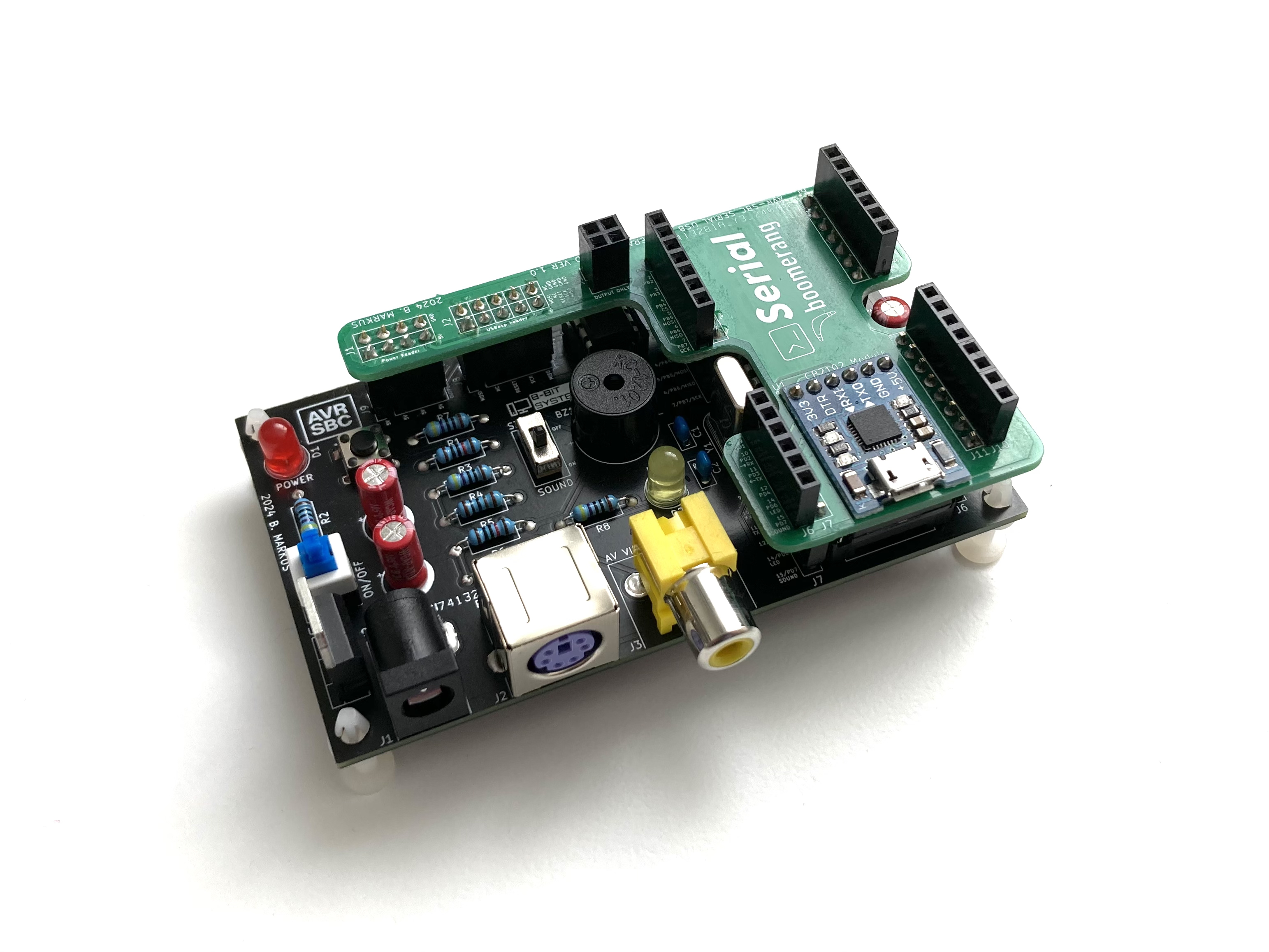
After a while, connecting an FTDI USB-serial cable to PD2 and PD3 every time I wanted to upload a program got old really fast. So I opened KiCad again and designed a small stackable expansion board - the Boomerang Shield.
Why boomerang? Because of the shape. It has cutouts for the crystal and capacitors, and it follows the contour of the pin headers on the main board. I didn't mean for it to look like a boomerang, it just happened that way. I didn't want to redesign it - this is already the third revision of the main board - so the name stuck.
The shields use the same 2.54mm pin headers as the main board and stack directly on top. Pin headers are also broken out on the shield itself so GPIO access is not lost.
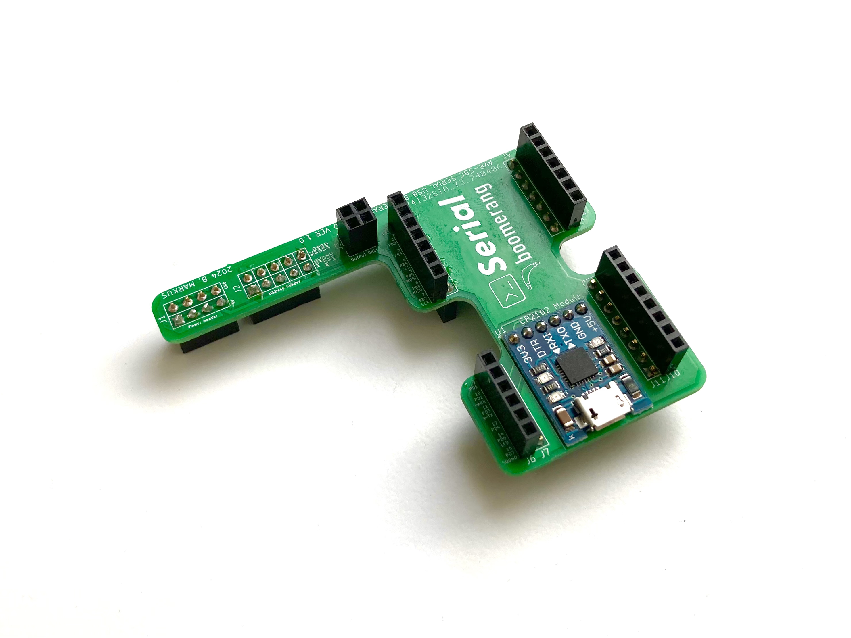
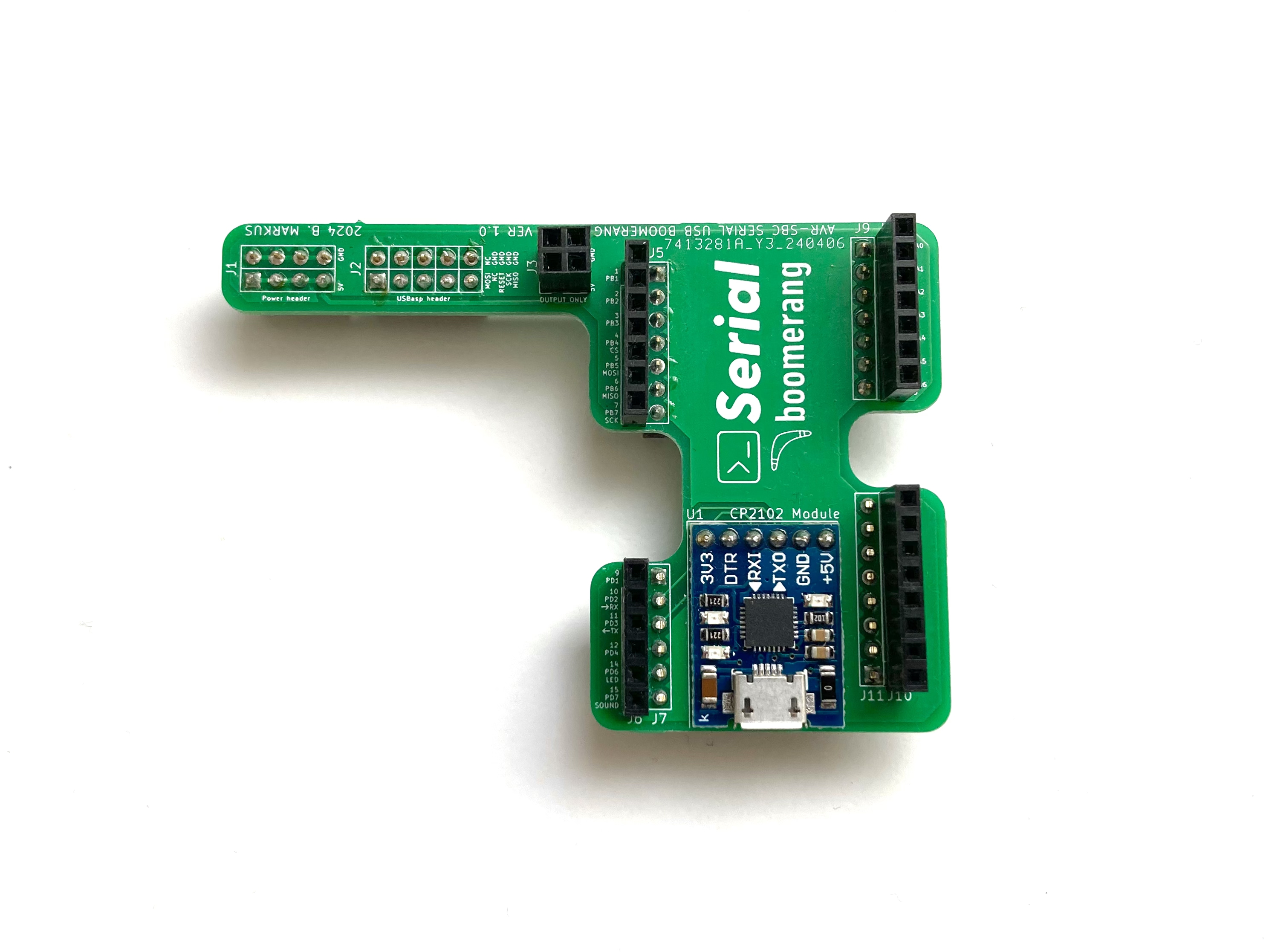
The serial boomerang shield is the official one. It carries a CP2102 USB-to-serial bridge module, connects to UART1 (PD2/PD3) of the AVR-SBC, and exposes a micro-USB connector. That's it - but now I can just leave it sitting on top of the board and upload programs with a single cable. Much better.
The KiCad project, schematic, and Gerber files for the serial boomerang shield are in the boomerang-shields/serial-boomerang-shield/ folder. There is also an empty boomerang shield template in boomerang-shields/empty-boomerang-shield-template/ if you want to design your own expansion.
Once I had the serial shield working, I started thinking about what else could plug into the same spot. The CP2102 module and an HC-06 Bluetooth Classic module have a very similar pinout - both are essentially a UART bridge. So I quickly wired one up on a perfboard with the same pin header footprint as the serial shield, plugged it in, and it worked.
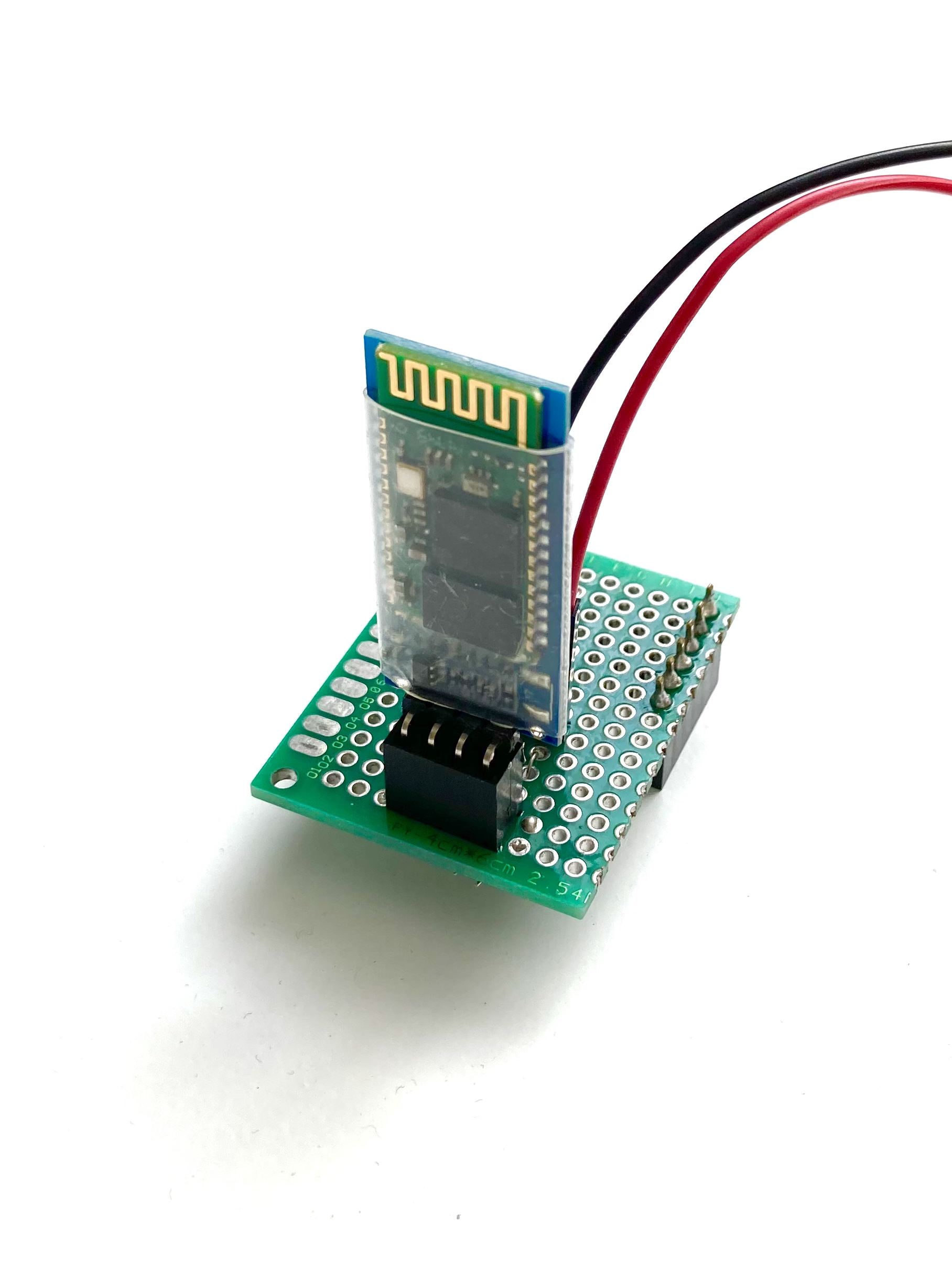
When the HC-06 is paired with a PC, it shows up as a virtual COM port via Bluetooth Classic SPP - exactly the same as the USB cable. That means I can upload BASIC programs to the AVR-SBC completely wirelessly. Which is, honestly, pretty amazing for a board built around an 8-bit microcontroller.
There is no official PCB design for the Bluetooth boomerang yet - it lives on a perfboard prototype for now. If I ever design it properly, I would probably use a better module, something like a Würth Elektronik Proteus-IV, a Skoll-I, or an ESP32-based module.
I also soldered together a small perfboard circuit with a seven segment display that stacks on top of the boomerang shield.
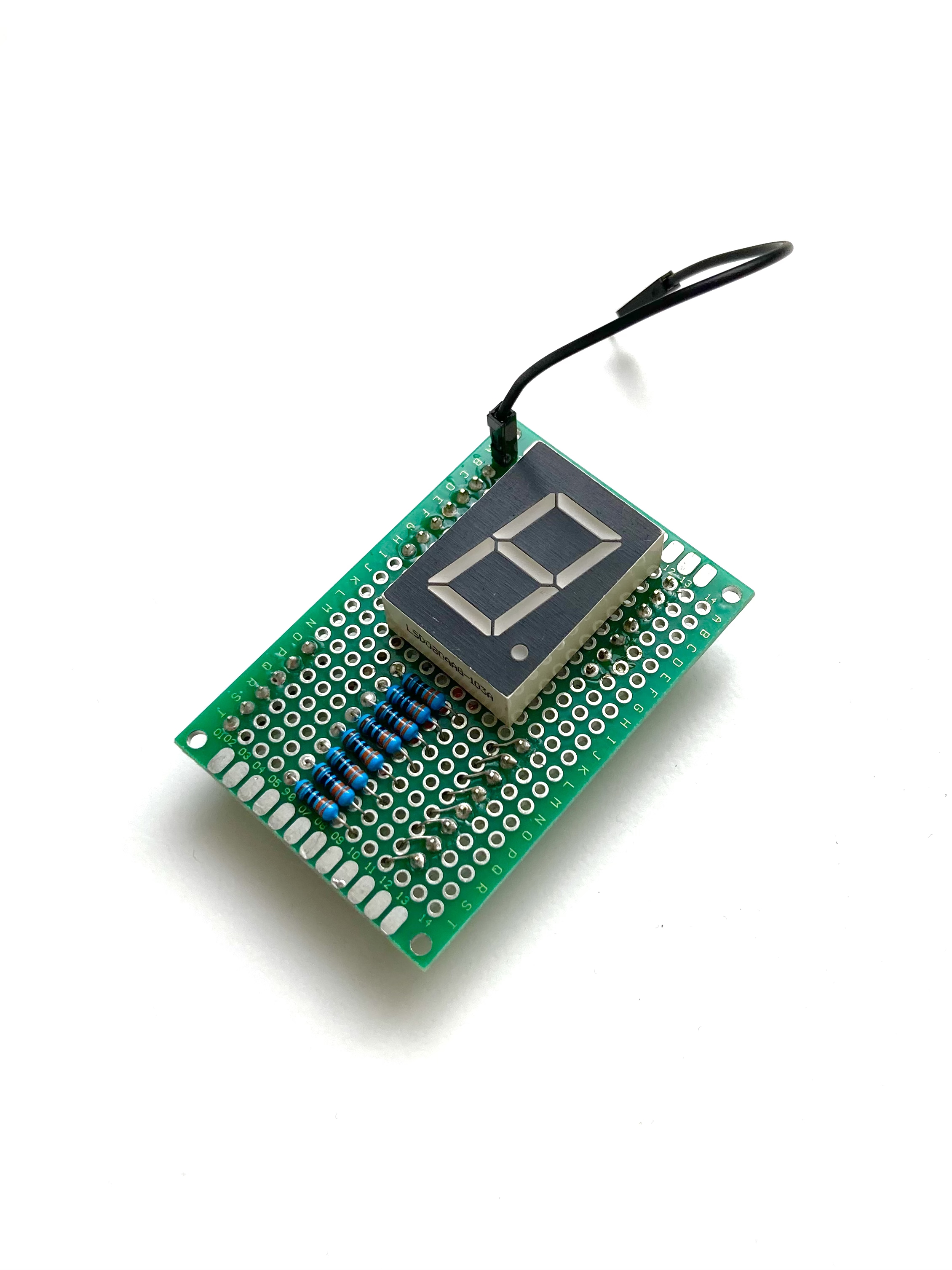
So at one point I had three layers: AVR-SBC → Serial Boomerang Shield → Seven Segment Extension. There is a BASIC example for it in the examples/ folder.
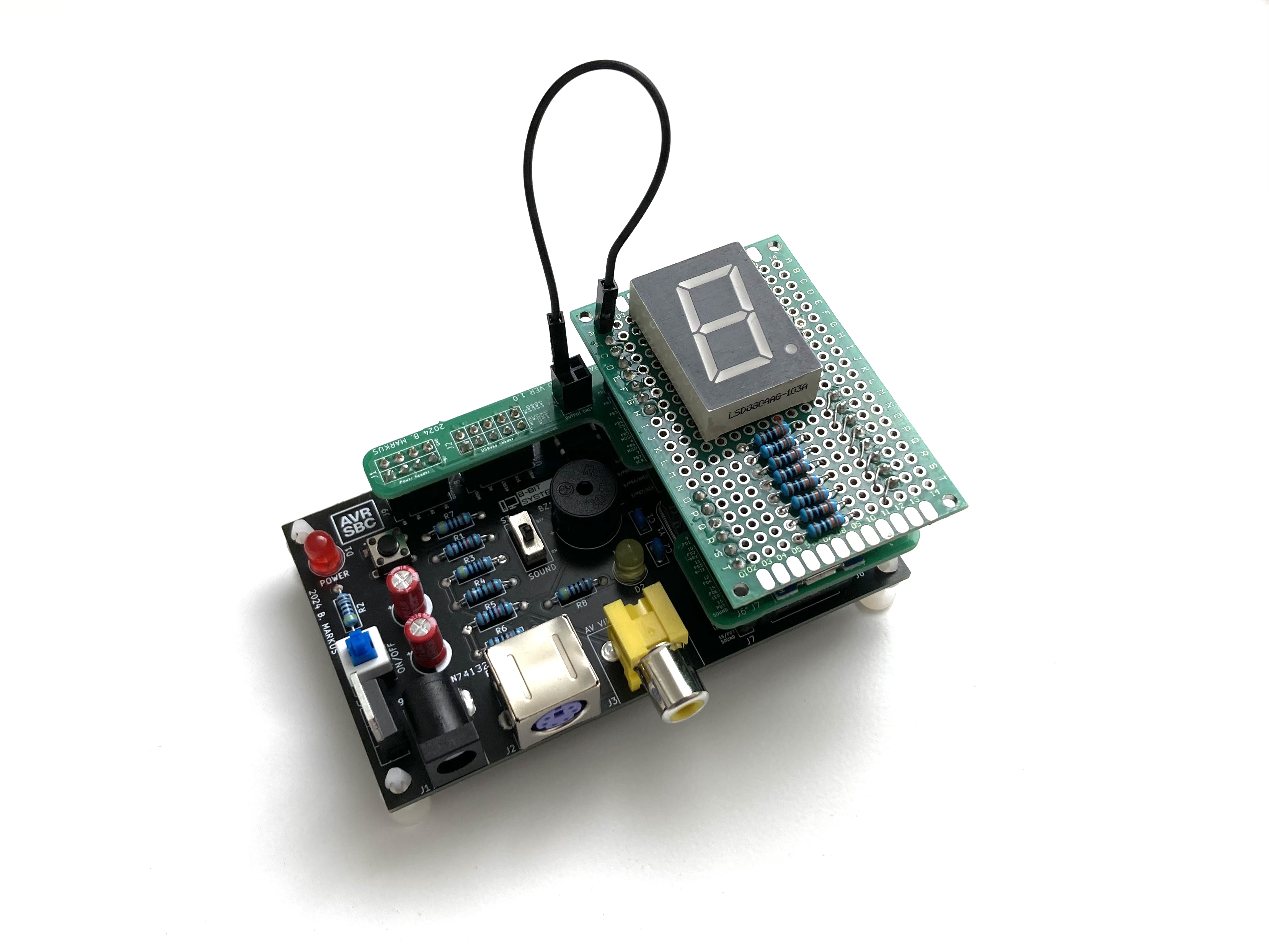
Like the Bluetooth shield, this one never got an official PCB design. It remains a perfboard prototype.
SBC Studio is a companion Python application for the AVR-SBC. It started as a simple serial uploader - basically just a way to type programs into the board really fast over UART1 without having to sit at a PS/2 keyboard. Over time it grew into something more, so I gave it a proper name.
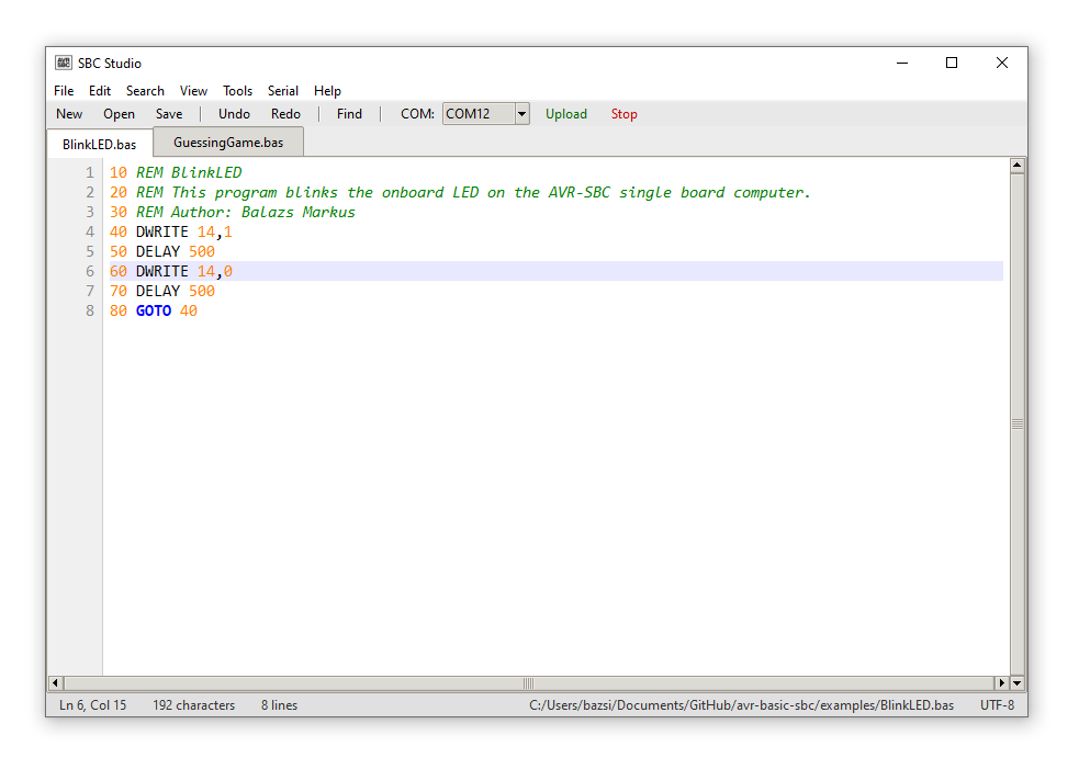
It requires Python 3 with pyserial. The bitmap tools also need Pillow, and the MIDI converter needs pretty_midi. Everything else is standard library.
pip install pyserial Pillow pretty_midi
python sbc-studio.py
The source is in pc-tools/sbc-studio/.
The main window is a lightweight .bas file editor with syntax highlighting, line numbers, tab support, find & replace, and undo/redo. It is nothing fancy, but it is comfortable enough for writing and editing Tiny BASIC programs.
The serial upload works by opening UART1 at 9600 baud and sending the program character by character - essentially simulating someone typing it in at the > prompt, just very fast. To upload, select your COM port from the toolbar, open or write a .bas file, and hit upload. The board receives it line by line exactly as if you had typed it yourself.
The keyboard layout for the PS/2 side (EN/DE/HU) is selected at firmware compile time, but the upload always goes through serial so the layout doesn't matter there.
This was a fun one to build. The Bitmap Editor takes any image file and converts it to a 128×64 monochrome bitmap suitable for the AVR-SBC screen. It has options for scaling, centering, dithering (Floyd-Steinberg), threshold control, rotation, flip, and background colour. The output is a standard 1-bit .bmp file.
The Bitmap Loader then uploads that .bmp to the AVR-SBC's external 25LC640 EEPROM via serial, using XPOKE commands split into batches. Once uploaded, a small BASIC program reads the bitmap back out with XPEEK and draws it pixel by pixel with DRAWPIX.
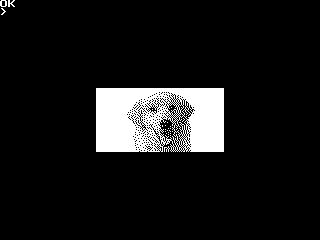
I included two examples in pc-tools/sbc-studio/sbc-studio-output/bitmap-editor/ - a photo of our dog and a flower.
The reason I like this so much is that the external EEPROM fits a 128×64 bitmap very comfortably, and you never have to take the chip out of the socket to reprogram it. Everything goes over serial.
At some point I realised that the TONEW command - which plays a tone at a given frequency and waits for it to finish - maps almost perfectly onto MIDI note data. So I built a converter that takes a single-track .mid file, extracts the notes, calculates frequencies and durations, and outputs a .bas file full of TONEW and DELAY statements that the AVR-SBC can play on its onboard buzzer.
The output is capped at around 5300 bytes to fit the BASIC program buffer. It is not going to replace a proper audio system, but hearing Für Elise come out of a piezo buzzer on a board you built yourself is genuinely satisfying. Two examples are included in pc-tools/sbc-studio/sbc-studio-output/midi-to-bas-converter/ - Für Elise and Ode to Joy.
Once the board was up and running I could finally sit down and actually write some programs for it in Tiny BASIC. The examples are all in the examples/ folder. They cover a bit of everything - games, graphics demos, sound, and hardware I/O.
All of them can be typed in at the > prompt directly, or uploaded from a PC using SBC Studio.
The simplest possible start. The PRINT command outputs text to the screen.
PRINT "HELLO"
The graphics library makes it easy to draw shapes directly from BASIC. These examples show off what the 320×240 display can do.
| File | Description |
|---|---|
ConcentricCircles.bas | Draws concentric circles filling the screen |
RandomRectangles.bas | Fills the screen with randomly placed rectangles |
Spirograph.bas | Spirograph-style pattern using lines and loops |
StarField.bas | Scrolling star field effect |
BouncingBall.bas | A ball bouncing around the screen |
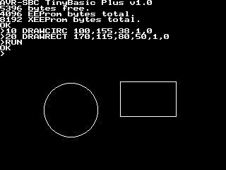
A few simple games that show off keyboard input, random numbers, and the graphics commands together.
| File | Description |
|---|---|
EatTheTargets.bas | Move a cursor around the screen and eat targets |
GuessTheNumber.bas | Classic guess the number game with hints |
SlotMachine.bas | An ASCII slot machine |
These use the TONE and TONEW commands to play melodies on the onboard buzzer. The MIDI converter in SBC Studio was used to generate the two classical pieces.
| File | Description |
|---|---|
CMajorPiano.bas | Plays a C major scale using the keyboard |
MelodyPlayer.bas | A simple melody player |
furelise.bas (generated) | Für Elise - in pc-tools/sbc-studio/sbc-studio-output/midi-to-bas-converter/ |
odetojoy.bas (generated) | Ode to Joy - in pc-tools/sbc-studio/sbc-studio-output/midi-to-bas-converter/ |
These examples interact with the GPIO pins and show how DWRITE, DREAD, and the EEPROM commands work in practice.
| File | Description |
|---|---|
BlinkLED.bas | Blinks the onboard yellow LED on PD6 using DWRITE |
SevenSegmentDisplay.bas | Drives a seven segment display connected to PORTC |
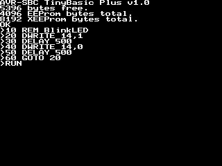
The board works, and it works reliably. But it is not perfect, and I know exactly where the rough edges are.
Decoupling capacitors - when I designed the board I was quite casual with component choices, and I skipped the per-chip decoupling capacitors. There are bulk capacitors for the microcontroller and the L7805CV, but they are not following the reference design. If I were to redesign the board I would definitely add proper decoupling caps on every supply pin.
No reverse polarity protection - the DC input has no protection diode. Plugging in the barrel jack the wrong way around will likely kill the board. A simple series diode or a P-channel MOSFET would fix this.
No Schottky diode on the ISP header - to prevent back-feeding the microcontroller through the programmer's VCC pin, I simply left the 5V pin on the ISP header unconnected. It works, but a proper Schottky diode would be a cleaner solution. As it stands, the board must always be powered through the DC barrel jack when programming.
PORTA reserved by the video system - as described in the Firmware section, the cycle-exact line rendering routine writes to the entire PORTA register using the AVR OUT instruction. This means PA0-PA6 cannot be used as GPIO without corrupting the video output, even though the pins are physically accessible on the J5 header. Getting 320×240 resolution with proper timing while also making PORTA available as GPIO is an unsolved problem for this project. If you have an idea, I would love to hear it.
Boomerang shields without official PCBs - the Bluetooth boomerang and the seven segment extension board are both perfboard prototypes. They work great but there are no KiCad files for them. At some point I would like to design proper PCBs for both - and when I do, I would probably swap the HC-06 for something more modern, like a Würth Elektronik Proteus-IV, a Skoll-I, or an ESP32-based module.
Single-track MIDI only - the MIDI to BAS converter in SBC Studio only handles single-track MIDI files. Multi-track files are not supported, which rules out a lot of MIDI content. Since the buzzer is monophonic anyway this is not a huge loss, but smarter track selection would be a nice improvement.
Auto-run from EEPROM - the firmware supports an ENABLE_EAUTORUN flag that automatically runs the program stored in internal EEPROM on boot, without showing the > prompt first. This is disabled by default but could be useful for standalone appliance-style deployments.
I started this project many years ago, then stopped, then restarted, then had a long pause. Many versions of KiCad were released in the meantime. AI systems started developing and becoming more and more advanced. And this project was still just there, waiting on a shelf somewhere between the other unfinished things. But occasionally when I came back to it, it made me very happy and I found it genuinely challenging.
Before this project I was usually defaulting to just using the Arduino framework - like the TVout-based firmware also did, and like many similar projects still do. But during this project I realized that with the power of real C and assembly you can get much further. Writing the line renderer in assembly, getting the timing right across three timers, squeezing everything into 16 KB of SRAM - none of that would have happened if I had stayed in Arduino land. So it was definitely a nice learning experience about myself too. Now there is no going back. Even the simplest things I do in low level C, and I have become really interested in assembly as well.
I am glad I have this project. I can't wait to see what the future brings with it - I am sure it will be exciting. And knowing myself, I will probably abandon it for a while again, and then one day come back and find something new to add. The hardware stays the same.
This project would not exist without these two:
Jörg Wolfram - AVR ChipBASIC The project that first showed me this kind of thing was possible on an AVR microcontroller.
Juan J. Martínez - DAN64 A beautifully executed AVR-based home computer that was a big influence on the direction of this project.
The firmware interpreter is based on a long chain of ports and adaptations:
The AVR-SBC version is a bare-metal port of TinyBasicPlus, adapted for the ATmega1284P with no Arduino framework and extended with graphics, sound, EEPROM, and serial commands.
Built with ❤️ and an 8-bit microcontroller
| Qty | Value | Footprint | References |
|---|---|---|---|
| 4 | 470R | StockLib:R_470_Axial_DIN0207 | R2, R3, R7, R8 |
| 4 | MountingHole_3.2mm_M3_DIN965 | MountingHole:MountingHole_3.2mm_M3_DIN965 | MH1, MH2, MH3, MH4 |
| 3 | 10k | StockLib:R_10k_Axial_DIN0207 | R1, R5, R6 |
| 2 | 22pF | Capacitor_THT:C_Rect_L4.6mm_W2.0mm_P2.50mm_MKS02_FKP02 | C1, C2 |
| 2 | LOGO | LOGO | G2, GRAPHICS2 |
| 1 | 0.1uF | Capacitor_THT:CP_Radial_D6.3mm_P2.50mm | C4 |
| 1 | 0.33uF | Capacitor_THT:CP_Radial_D6.3mm_P2.50mm | C3 |
| 1 | 16 MHz | Crystal:Crystal_HC49-U_Vertical | Y1 |
| 1 | 1k | StockLib:R_1k_Axial_DIN0207 | R4 |
| 1 | 25LC640 | Package_DIP:DIP-8_W7.62mm | U3 |
| 1 | 4.7uF | Capacitor_THT:CP_Radial_D6.3mm_P2.50mm | C5 |
| 1 | ATmega1284P-P | Package_DIP:DIP-40_W15.24mm | U1 |
| 1 | Button TACT 6x6mm | StockLib:Button TACT 6x6mm | S1 |
| 1 | Buzzer 1201 | StockLib:Buzzer 1201 | BZ1 |
| 1 | DC-005 Power Jack | StockLib:DC-005 Power Jack | J1 |
| 1 | L7805 | Package_TO_SOT_THT:TO-220-3_Vertical | U2 |
| 1 | LED 5mm RED | StockLib:LED_D5.0mm_RED | D1 |
| 1 | LED 5mm YELLOW | StockLib:LED_D5.0mm_YELLOW | D2 |
| 1 | PS/2 keyboard port | StockLib:PS2-connector-keyboard | J2 |
| 1 | Port A | Connector_PinHeader_2.54mm:PinHeader_1x07_P2.54mm_Vertical | J5 |
| 1 | Port B | Connector_PinHeader_2.54mm:PinHeader_1x07_P2.54mm_Vertical | J4 |
| 1 | Port C | Connector_PinHeader_2.54mm:PinHeader_1x08_P2.54mm_Vertical | J6 |
| 1 | Port D | Connector_PinHeader_2.54mm:PinHeader_1x06_P2.54mm_Vertical | J7 |
| 1 | Power output header | Connector_PinHeader_2.54mm:PinHeader_2x04_P2.54mm_Vertical | J9 |
| 1 | RCA Video Jack | StockLib:RCA Video Jack | J3 |
| 1 | Slide Switch SS12D00 | StockLib:Slide Switch SS12D00 | S3 |
| 1 | Toggle Switch 7x7mm | StockLib:Toggle Switch 7x7mm | S2 |
| 1 | USBasp header | Connector_PinHeader_2.54mm:PinHeader_2x05_P2.54mm_Vertical | J8 |
It measures 94 × 55 mm and has 2 copper layers, 1.6 mm thick.
38 parts, built around the ATMEGA1284P-PU, 25LC640-E/P and L7805. The full list of its parts is on this page, with links to each part's symbol and footprint where PCBKit's library has them.
From the bazsimarkus/avr-basic-sbc repository on GitHub, at the commit this page was made from: the board is schematic/avr-basic-sbc.kicad_pcb and its schematic boomerang-shields/emtpy-boomerang-shield-template/emtpy-boomerang-shield-template.kicad_sch. PCBKit opens the board in the browser, with nothing to install.
Its repository states no licence, so its author keeps all rights: ask bazsimarkus before reusing the design.
bazsimarkus/avr-basic-sbc
An ATmega1284P-based single board computer with composite video output, PS/2 keyboard input, running Tiny BASIC.

zachrjt/digital-voltages-ps
Fixed 3.3V and 5V voltage power supply with voltage and current readout


ThKattanek/1541-rebuild
Ersetzt den Analogteil einer Floppy 1541 oder 1541-II durch ein µC.

hbekel/keyman64
programmable C64 keyboard interceptor and hardware control system
