
2 layers126 × 39.5 mm
Pot sensor
Manolets/potsensor_schematics
This repo contains the KiCad project files for a battery powered plant sensor.
55 parts
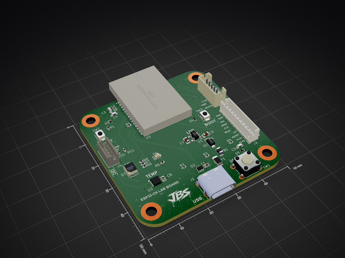
custom esp32-c6 development board with rgb status led, user input, i2c expansion, oled support, and onboard environmental sensing.
ESP32-C6 is an open-source printed circuit board by Batterhead221, from the Batterhead221/esp32-c6_microcontroller repository on GitHub. It is a 4-layer board of 50 × 50 mm with 42 parts on 44 nets, routed with 408 tracks and 75 vias.
It is built around the ESP32-C6-WROOM-1-N8, HDC3020DEFR and ESD9B3.3S, with the USBLC6-2P6 among its other parts. Its parts include 11 resistors, 8 capacitors, 7 diodes, 4 connectors and 3 ICs. It belongs with the lEDs and displays and microcontroller boards boards and the ESP32 and RISC-V boards of this library.


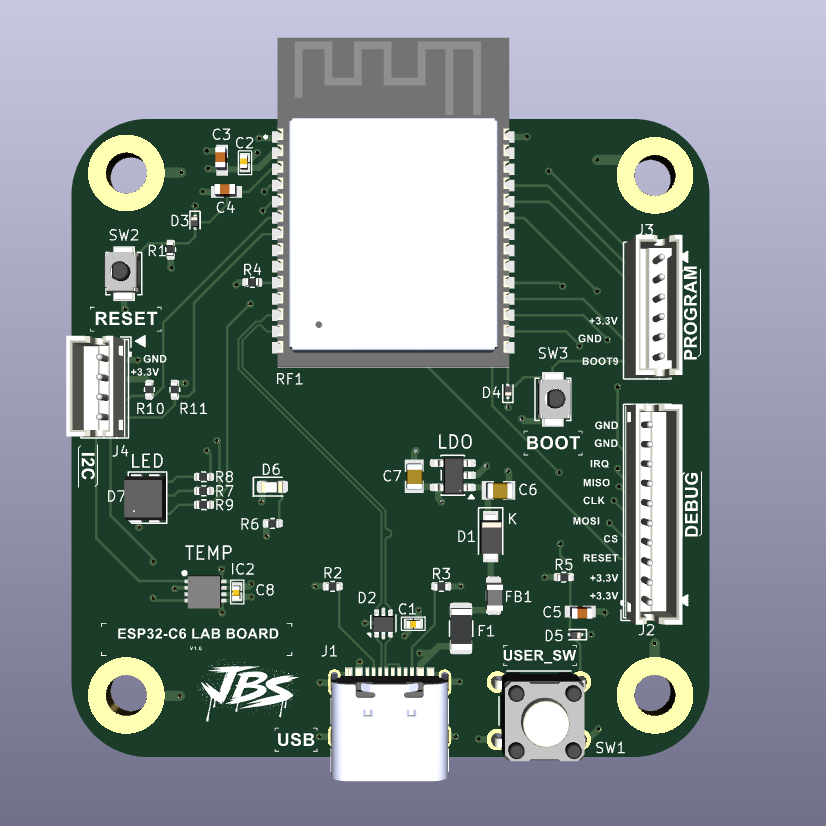
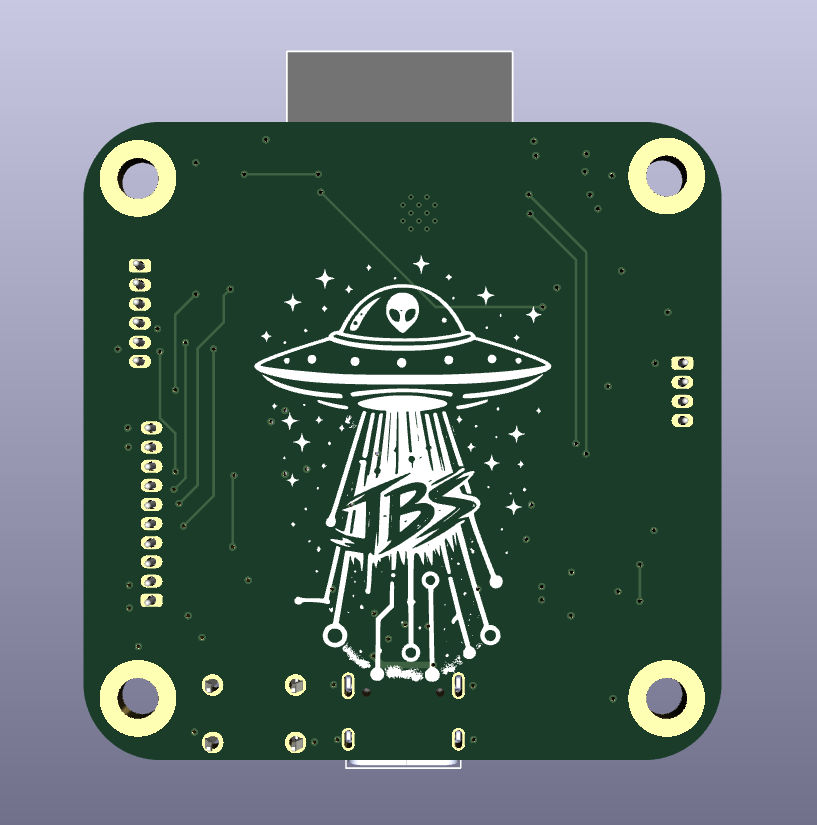
Custom ESP32-C6 development board with USB-C power, RGB status LED, user input, I2C expansion, OLED support, UART programming access, and onboard temperature/humidity sensing.
This board is a small ESP32-C6 bring-up and sensor demo platform. It was designed to verify core power, boot/programming flow, GPIO, RGB LED control, I2C device detection, OLED output, and live environmental sensor readings.
Bring-up demo verified.
The board has successfully run a combined test with:
USB-C / bench power
        ↓
ESP32-C6_MICROCONTROLLER
        ↓ I2C
OLED display + temp/humidity sensor
        ↓
bring-up demo / serial debug output| Item | Value |
|---|---|
| MCU | ESP32-C6 |
| Main rail | +3.3V |
| Power input | USB-C |
| Programming path verified | UART through J3 program header |
| Display interface | I2C OLED |
| Sensor interface | I2C temp/humidity sensor |
| OLED address | 0x3C |
| Temp/humidity sensor address | 0x44 |
| RGB LED behavior | Active-low |
| Board role | ESP32-C6 bring-up/demo board |
0x3C0x44| GPIO | Function |
|---|---|
| GPIO3 | RGB red |
| GPIO4 | RGB green |
| GPIO5 | RGB blue |
| GPIO23 | User switch |
| GPIO6 | I2C SDA |
| GPIO7 | I2C SCL |
The RGB LED is active-low.
GPIO LOW  → LED color ON
GPIO HIGH → LED color OFF
Firmware should invert the LED logic when controlling the status LED.
The following I2C devices were detected during bring-up:
| Address | Device |
|---|---|
0x3C | OLED display |
0x44 | Temperature/humidity sensor |
Example live reading from bring-up:
Temperature: 29.2 C
Humidity:    35.0 %RH
UART programming through the J3 program header is working.
Working connections:
| USB-UART adapter | ESP32-C6 board |
|---|---|
| TX | ESP_RXD |
| RX | ESP_TXD |
| GND | GND |
Current working upload sequence:
Native USB enumeration still needs separate debug and validation.
Current programming flow uses UART through the J3 program header.
0x3C.0x44.Expected image paths for GitHub README rendering:
Outputs/
  IMG/
    3D-T.png
    3D-B.png
    SCHEMATIC.png
    L1-SIG.png
L2-GND.pngESP32-C6_MICROCONTROLLER is a low-voltage development board. Verify regulator output, USB wiring, and UART adapter voltage level before connecting external hardware.
Designed & engineered by Brandon Shelly.
| Qty | Value | Footprint | References |
|---|---|---|---|
| 4 | 1K | Resistor_SMD:R_0402_1005Metric | R6, R7, R8, R9 |
| 4 | M3 | PCM_SL_Mechanical:MountingHole_3.2mm_Pad | H1, H2, H3, H4 |
| 3 | 100N | C0402C221K1HACAUTO:CAP 0402 | C1, C2, C8 |
| 3 | 10K | Resistor_SMD:R_0402_1005Metric | R1, R4, R5 |
| 3 | 1U | C1608X6S0G226M080AC:CAP 0603 | C3, C4, C5 |
| 3 | ESD9B3.3 | Diode_SMD:D_SOD-923 | D3, D4, D5 |
| 2 | 1U | GRM21BR71A105KA01L:1UF 0805 | C6, C7 |
| 2 | 2K2 | Resistor_SMD:R_0402_1005Metric | R10, R11 |
| 2 | 5K1 | Resistor_SMD:R_0402_1005Metric | R2, R3 |
| 1 | Button_Switch_SMD:SW_SPST_B3U-1000P | SW3 | |
| 1 | 1A | Fuse:Fuse_1206_3216Metric | F1 |
| 1 | 1N5817 | Diode_SMD:Nexperia_CFP3_SOD-123W | D1 |
| 1 | 22 | Inductor_SMD:L_0805_2012Metric | FB1 |
| 1 | ESP32-C6-WROOM-1-N8 | ESP32-C6-WROOM-1-N8:XCVR_ESP32-C6-WROOM-1-N8 | U3 |
| 1 | GREEN | LED_SMD:LED_0603_1608Metric | D6 |
| 1 | HDC3020DEFR | HDC3020DEFR:SON50P250X250X80-9N-D | U2 |
| 1 | LDO | Package_TO_SOT_SMD:SOT-23-5 | U1 |
| 1 | PROGRAM | Connector_JST:JST_ZH_B6B-ZR_1x06_P1.50mm_Vertical | J3 |
| 1 | RBG_LED | LED_SMD:LED_Cree-PLCC4_3.2x2.8mm_CCW | D7 |
| 1 | RESET | Button_Switch_SMD:SW_SPST_B3U-1000P | SW2 |
| 1 | S2C | Connector_JST:JST_ZH_B4B-ZR_1x04_P1.50mm_Vertical | J4 |
| 1 | SWD | Connector_JST:JST_ZH_B10B-ZR_1x10_P1.50mm_Vertical | J2 |
| 1 | SW_DPST | Button_Switch_THT:SW_TH_Tactile_Omron_B3F-100x | SW1 |
| 1 | USBLC6-2P6 | Package_TO_SOT_SMD:SOT-666 | D2 |
| 1 | USB_C | Connector_USB:USB_C_Receptacle_G-Switch_GT-USB-7010ASV | J1 |
It measures 50 × 50 mm and has 4 copper layers, 1.6 mm thick.
42 parts, built around the ESP32-C6-WROOM-1-N8, HDC3020DEFR, ESD9B3.3S and USBLC6-2P6. The full list of its parts is on this page, with links to each part's symbol and footprint where PCBKit's library has them.
From the Batterhead221/esp32-c6_microcontroller repository on GitHub, at the commit this page was made from: the board is ECAD/ESP32-C6.kicad_pcb and its schematic ECAD/ESP32-C6.kicad_sch. PCBKit opens the board in the browser, with nothing to install.
Its repository states no licence, so its author keeps all rights: ask Batterhead221 before reusing the design.
Manolets/potsensor_schematics
This repo contains the KiCad project files for a battery powered plant sensor.


yogith-mr/ESP32C6-DEMO-BOARD
Custom ESP32-C6 development board designed using KiCad, including schematic capture and PCB layout. Focused on embedded systems and IoT applications with proper routing, power design, and signal integrity.


AlfredoSystems/Rotini-Hardware
📖 Documentation: https://www.alfredosys.com/Rotini-Hardware/ (pinout, power limits, flashing ExpressLRS, first Arduino upload)

