4 layers80 × 35 mm

 Batterhead221/brain_board
Custom STM32H753 brain board with USB-C power/input selection, 3.3V buck regulation, microSD, CAN, RS-485, FRAM, flash, debug/programming access, and expansion connectors.
Brain board is an open-source printed circuit board by Batterhead221, from the Batterhead221/brain_board repository on GitHub, published under the MIT licence. It is a 4-layer board of 99.5 × 92.3 mm with 131 parts on 161 nets, routed with 1,217 tracks and 357 vias.
It is built around the THVD1450DRBR, W25Q128JVEIM TR and CGA5L1X7R1H106K160AC, with the B3U-1100P and ABM3B-8.000MHZ-B2-T among its other parts. Its parts include 49 capacitors, 37 resistors, 13 connectors, 7 ICs and 5 diodes. It belongs with the interfaces and adapters and robots and motor control boards and the STM32 boards of this library.


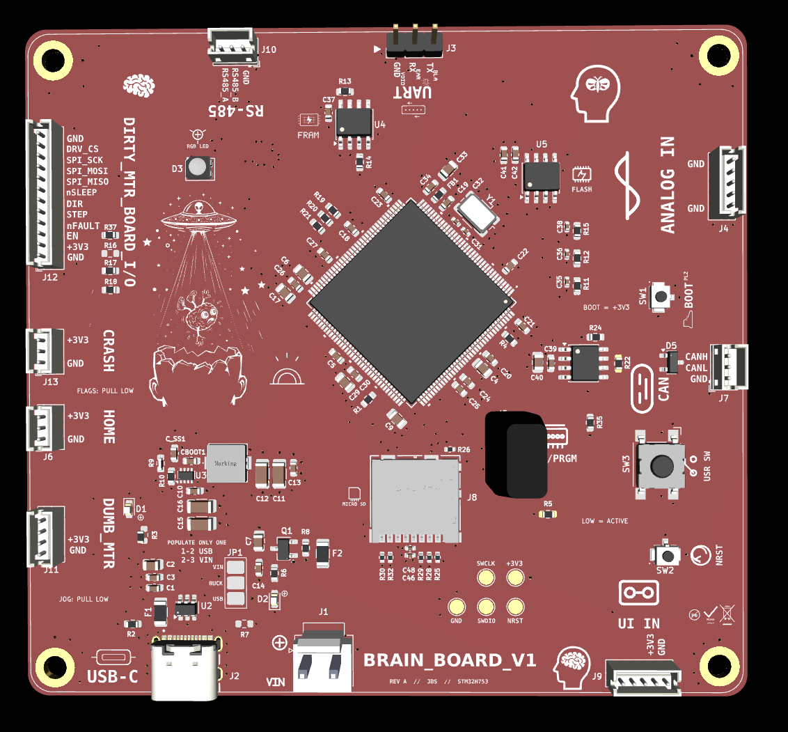
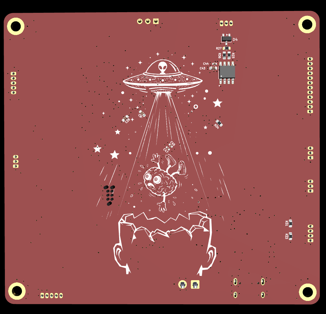
Custom STM32H753 main controller board for modular motion, control, storage, communication, and daughter-board expansion.
BRAIN_BOARD is the clean logic/control board in a modular hardware system. It handles MCU control, communication, debugging/programming, storage, sensor inputs, and daughter-board interfaces. Noisy motor power and phase switching are kept on external boards such as DIRTY_MTR_BOARD.
In progress. Main controller schematic and PCB layout under development/review.
Host / USB / RS485 / CAN
        ↓
BRAIN_BOARD
        ↓ STEP / DIR / SPI / GPIO
DIRTY_MTR_BOARD / daughter boards
        ↓
Motor / sensors / external hardware
BRAIN_BOARD does not directly drive stepper motor coils. Motor current, switching, and noisy power handling belong on dedicated daughter boards.
| Item | Value |
|---|---|
| MCU | STM32H753ZITx |
| Package | LQFP-144 |
| Logic rail | +3.3V |
| USB | USB-C |
| External communication | RS485, CAN |
| Storage | microSD |
| Nonvolatile memory | SPI FRAM |
| Debug/programming | SWD / debug UART headers |
| Daughter-board support | Motor/control, analog I/O, manual jog, external flags |
| Power options | USB or VIN path with jumper selection |
| Board role | Main controller / system brain |
BRAIN_BOARD is intended to keep logic power clean and separate from noisy motor power.
USB-C / VIN input path
        ↓
power selection / protection
        ↓
+3.3V logic rail
        ↓
STM32H753 + memory + communication interfaces
Motor power is not generated or switched directly on BRAIN_BOARD.
Planned or related daughter boards include:
Manual jog style inputs are intended to be active-low. External buttons pull the signal to GND when pressed.
Design priorities:
Expected image paths for GitHub README rendering:
Outputs/
  IMG/
    3D-T.png
    3D-B.png
    SCHEMATIC.png
    L1-SIG.png
    L2-3V3.png
    L3-GND.png
L4-MIX.pngBRAIN_BOARD is a low-voltage controller PCB. Motor power, external loads, and high-current switching should be handled on separate boards with appropriate power routing, protection, and review.
| Qty | Value | Footprint | References |
|---|---|---|---|
| 22 | 100nF | CAPS:C_0603_1608Metric | C1, C10, C13, C14, C18, C19, C20, C21, C22, C23, C24, C25, C26, C27, C28, C30 +6 |
| 10 | 10K | RESISTOR:R_0603 | R1, R5, R8, R10, R13, R14, R31, R33, R34, R35 |
| 7 | 100 | RESISTOR:R_0603 | R11, R12, R15, R16, R17, R18, R37 |
| 5 | 10nF | CAPS:C_0402_1005Metric | C35, C36, C38, C45, C47 |
| 5 | 47K | RESISTOR:R_0402_1005Metric | R25, R28, R29, R30, R32 |
| 4 | MountingHole_Pad | MountingHole:MountingHole_3.2mm_M3_ISO14580_Pad_TopBottom | H1, H2, H3, H4 |
| 3 | 2.2µF | CAPS:C_0805_2012Metric | C4, C6, C9 |
| 3 | 470 | RESISTOR:R_0603 | R19, R20, R21 |
| 2 | 0 | RESISTOR:R_0603 | R23, R36 |
| 2 | 100nF | CAPS:C_0402_1005Metric | C44, C46 |
| 2 | 10µF | CAPS:C_0805_2012Metric | C2, C7 |
| 2 | 10µF | CAPS:C_1206_3216Metric | C15, C16 |
| 2 | 120 | RESISTOR:R_0603 | R22, R27 |
| 2 | 1206 | FUSE:Fuse_1206_3216Metric | F1, F2 |
| 2 | 18pF | CAPS:C_0402_1005Metric | C31, C32 |
| 2 | 1µF | CAPS:C_0805_2012Metric | C29, C33 |
| 2 | 1µF | CAPS:C_0603_1608Metric | C3, C42 |
| 2 | 22µF | CAPS:C_1206_3216Metric | C11, C12 |
| 2 | 4.7µF | CAPS:C_0805_2012Metric | C17, C40 |
| 2 | 5.1K | RESISTOR:R_0603 | R2, R7 |
| 2 | 750 | RESISTOR:R_0603 | R3, R6 |
| 2 | B3U-1100P | SWITCH_BUTTON:SW_B3U-1100P | SW1, SW2 |
| 1 | +5V_SIG | LED:LED_0603_1608Metric | D1 |
| 1 | 100NF | CAPS:C_0603_1608Metric | C39 |
| 1 | 1040310811 | SD_CARD:104031-0811_MOL | J8 |
| 1 | 10K | RESISTOR:R_0402_1005Metric | R26 |
| 1 | 10µF | CAPS:C_0603_1608Metric | C43 |
| 1 | 1µF | CAPS:C_0402_1005Metric | C48 |
| 1 | 3.3V | TEST_POINT:TestPoint_Pad_D2.0mm | TP1 |
| 1 | 31.6K | RESISTOR:R_0603 | R9 |
| 1 | 33nF | CAPS:C_0603_1608Metric | C_SS1 |
| 1 | 4.7K | RESISTOR:R_0603 | R24 |
| 1 | 4.7µH | INDUCTOR:L_SRP5030TA4R7M | L1 |
| 1 | 5K1 | RESISTOR:R_0603 | R4 |
| 1 | ABM3B-8.000MHZ-B2-T | CRYSTAL:Crystal_SMD_Abracon_ABM3B-4Pin_5.0x3.2mm | Y1 |
| 1 | AO3407A (SOT-23-3) | SOT:TSOT-23 | Q1 |
| 1 | BEEFY_JUMPER | JUMPER:PWR_JMP_BEEFY | JP1 |
| 1 | CLV1L-FKB | LED:LED_Cree-PLCC4_3.2x2.8mm_CCW | D3 |
| 1 | CRASH | JST_ZH:JST_ZH_B3B-ZR_1x03_P1.50mm_Vertical | J13 |
| 1 | DBG_NRST | TEST_POINT:TestPoint_Pad_D2.0mm | TP4 |
| 1 | DBG_SWCLK | TEST_POINT:TestPoint_Pad_D2.0mm | TP5 |
| 1 | DBG_SWDIO | TEST_POINT:TestPoint_Pad_D2.0mm | TP3 |
| 1 | FERRITE_BEAD | FUSE:Fuse_0603_1608Metric | FB1 |
| 1 | FM25V20A-G_(SOIC-8) | SOIC:SOIC-8_3.9x4.9mm_P1.27mm | U4 |
| 1 | GND | TEST_POINT:TestPoint_Pad_D2.0mm | TP2 |
| 1 | HOME | JST_ZH:JST_ZH_B3B-ZR_1x03_P1.50mm_Vertical | J6 |
| 1 | JST_EH-14 | JST_ZH:JST_ZH_B12B-ZR_1x12_P1.50mm_Vertical | J12 |
| 1 | LED_GREEN | LED:LED_0603_1608Metric | D2 |
| 1 | LQFP-144 | MCU:LQFP144-20x20mm | U1 |
| 1 | MTA-4 | JST_ZH:JST_ZH_B4B-ZR_1x04_P1.50mm_Vertical | J11 |
| 1 | MTA-5 | JST_ZH:JST_ZH_B5B-ZR_1x05_P1.50mm_Vertical | J4 |
| 1 | PH-3 | JST_ZH:JST_ZH_B3B-ZR_1x03_P1.50mm_Vertical | J10 |
| 1 | SM24CANB-02HTG (SOT-23-3) | ESP32-C6_PROJECT:SOT-23 | D5 |
| 1 | SM712_SOT23 | SOT:SOT-23-3 | D4 |
| 1 | TC2030-NL | TAG-CONNECT:Tag-Connect_TC2030-IDC-NL_2x03_P1.27mm_Vertical | J5 |
| 1 | THVD1450DR | RS485:SOIC127P599X175-8N | U7 |
| 1 | TJA1051T/3_(SOIC-8) | SOIC:SOIC-8_3.9x4.9mm_P1.27mm | U6 |
| 1 | TPS62933DRLR | BUCK:SOT-583-8 | U3 |
| 1 | USB4105-GF-A (USB-C) | USB:GCT_USB4105-GF-A | J2 |
| 1 | USBLC6-2SC6_(SOT-23-6) | ESP32-C6_PROJECT:SOT-23-6 | U2 |
| 1 | VH | JST_VH:JST_VH_B2P-VH_1x02_P3.96mm_Vertical | J1 |
| 1 | W25Q128JVEIM_TR | SOIC:SOIC-8-1EP_3.9x4.9mm_P1.27mm_EP2.29x3mm | U5 |
| 1 | ZH-3 | PIN_HEADER:PinHeader_1x03_P2.54mm_Vertical | J3 |
| 1 | ZH-3 | JST_ZH:JST_ZH_B3B-ZR_1x03_P1.50mm_Vertical | J7 |
| 1 | ZH-5 | JST_ZH:JST_ZH_B5B-ZR_1x05_P1.50mm_Vertical | J9 |
| 1 | ~ | BUTTON_SWITCH:SW_SPST_Omron_B3FS-100xP | SW3 |
It measures 99.5 × 92.3 mm and has 4 copper layers, 1.6 mm thick.
131 parts, built around the THVD1450DRBR, W25Q128JVEIM TR, CGA5L1X7R1H106K160AC and B3U-1100P. The full list of its parts is on this page, with links to each part's symbol and footprint where PCBKit's library has them.
From the Batterhead221/brain_board repository on GitHub, at the commit this page was made from: the board is ECAD/BRAIN_BOARD.kicad_pcb and its schematic ECAD/BRAIN_BOARD.kicad_sch. PCBKit opens the board in the browser, with nothing to install.
Its repository publishes it under the MIT licence: you may reuse it on that licence's terms (keep the author's notice, and for a copyleft licence share your changes alike).


EwoudVV/ducktop2
An open-source 16-inch laptop designed from scratch.

fl4p/buck-tpsm33610
3-36 V to 3.3 V, 1 A break-out for the TI TPSM33610S3Q buck module. 2-layer, 9.01 x 12.525 mm, fully generated from Python. UNBUILT.


