2 layers167.2 × 120.7 mm
Dyad main right
bathoorn/dyad-keyboard
Split keyboard: KiCad PCB, 3D-printed case, QMK firmware. Rotary encoder ring per half — round display left, Cirque trackpad right. Bare RP2040 per side.
149 partsMIT

 bathoorn/dyad-keyboard
Split keyboard: KiCad PCB, 3D-printed case, QMK firmware. Rotary encoder ring per half — round display left, Cirque trackpad right. Bare RP2040 per side.
Dyad controller is an open-source printed circuit board by bathoorn, from the bathoorn/dyad-keyboard repository on GitHub, published under the MIT licence. It is a 2-layer board of 35 × 57 mm with 44 parts on 72 nets, routed with 1,019 tracks and 244 vias.
It is built around the RP2040, W25Q128JVSIQ and USBLC6-2SC6, with the HC-FPC-0.5-20P-FH20, HC-FPC-0.5-14P-FH20 and SS34 among its other parts. Its parts include 17 capacitors, 7 resistors, 6 connectors, 4 ICs and 2 switches. It belongs with the keyboards and input and lEDs and displays boards and the RP2040 boards of this library.


A split keyboard with a rotary encoder ring on each half — a round display inside the left ring, a circular trackpad inside the right. Custom PCBs in KiCad, a 3D-printed case, running QMK.
Dyad: a pair. Two halves, two dials, two boards.
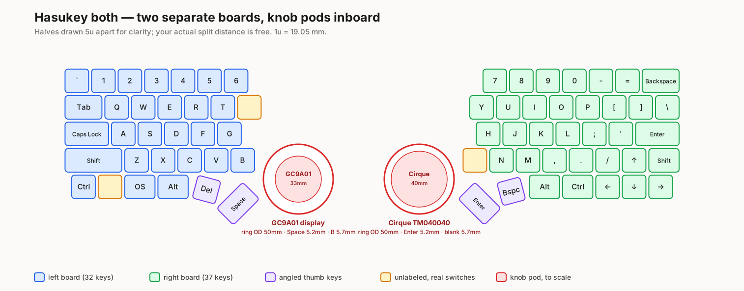
69 keys, 32 left and 37 right, row-staggered. Bare RP2040 on each side.
"A display on top of a knob" normally means the display rotates, which needs a slip ring or a wire loom that survives unlimited rotation.
Dyad inverts it. The display and trackpad are static; the ring rotates around them. A fixed centre post rises through the bearing bore and cantilevers the sensor above the moving parts, so no wire ever moves. Visually and ergonomically it reads as a knob with a screen on top — electrically it's a static part with a ring turning beneath it.
Both rings are 50 mm outside diameter, so the halves are a matched pair.
| MCU | Bare RP2040, one shared controller module used by both halves |
| Left pod | GC9A01 1.28" round LCD, 240×240, SPI |
| Right pod | Cirque Pinnacle TM040040, 40 mm |
| Encoders | EC11, driven by a ring gear from the rotating ring |
| Switches | MX hot-swap, Kailh sockets |
| Per-key RGB | SK6812MINI-E — footprints fitted, populated only if wanted |
| Split link | USB-C to USB-C, half-duplex serial |
Four board designs: one controller module (the only board needing an assembly service), two asymmetric main PCBs, and two knob-module variants.
| Phase | State |
|---|---|
| 0 — Layout | Done. Validated against printed 1:1 mock-ups. |
| 1 — Bench bring-up | Partial. Toolchain, flashing, encoder and Cirque all pass. Display, ribbon-SPI, split and current tests await parts. |
| 2 — Knob mechanism | Not started. |
| 3 — KiCad | Main PCBs generated and placed; controller pin assignment and BOM settled. |
| 4 — Case | Not started. Board outlines and plate cutouts exported for it. |
The main PCBs are a placement scaffold, not a finished layout. DRC reports 195 violations on the left and 253 on the right, none electrical (shorts, clearance, mask bridges). The 32 and 37 errors are all diode/switch courtyard overlaps from the deliberate diode-under-switch placement; the rest is silkscreen. Routing is incomplete, notably the angled thumb keys.
docs/          PLAN.md, WORKFLOW.md, CONTROLLER.md, PHASE1.md, TOOLS.md,
               GIT.md, plus printable 1:1 mock-ups
hardware/
  interface.yaml   the contract between the PCB and case designs
  layout/          KLE source of truth, parser, pod-placement solver
  pcb-main-*/      the two main PCBs (generated)
  pcb-controller/  controller module, and the vendored RP2040 reference
  outlines/        board outlines, plate cutouts and STEP, for the case
firmware/      QMK external userspace
Nearly everything under hardware/ is generated from the KLE layout.
Regenerate with hardware/generate_main_pcbs.py, export_outlines.py and
export_plate.py — see docs/TOOLS.md for the environment they need.
qmk config user.qmk_home=~/qmk_firmware
qmk config user.overlay_dir=$PWD/firmware
ln -sfn $PWD/firmware/keyboards/dyad ~/qmk_firmware/keyboards/dyad
qmk compile -kb dyad/split -km default
The symlink is required: QMK's external userspace holds keymaps and build targets, but not keyboards.
dyad/proto and dyad/split are Phase 1 bring-up targets for dev boards, not
the shipping keyboard definition.
MIT — see LICENSE.
hardware/pcb-controller/upstream/ vendors
RP2040-designguide
(MIT, © 2021 Sleepdealer) as a read-only reference. The key layout originates
from the Hasukey KLE layout.
| Qty | Value | Footprint | References |
|---|---|---|---|
| 10 | 100nF | Capacitor_SMD:C_0402_1005Metric | C1, C5, C6, C9, C10, C11, C12, C13, C14, C15 |
| 4 | 1uF | Capacitor_SMD:C_0402_1005Metric | C4, C8, C16, C17 |
| 4 | MountingHole_2.2mm_M2_Pad | MountingHole:MountingHole_2.2mm_M2_Pad | H1, H2, H3, H4 |
| 3 | 1k | Resistor_SMD:R_0402_1005Metric | R1, R2, R7 |
| 2 | 15pF | Capacitor_SMD:C_0402_1005Metric | C2, C3 |
| 2 | 27R | Resistor_SMD:R_0603_1608Metric | R5, R6 |
| 2 | 500mA | Fuse:Fuse_1206_3216Metric | F1, F2 |
| 2 | 5k1 | Resistor_SMD:R_0402_1005Metric | R3, R4 |
| 2 | HC-FPC-0.5-20P-FH20 | dyad:FPC-SMD_20P-P0.50_HC-FPC-0.5-20P-FH20 | J6, J7 |
| 2 | USB-C split link | dyad:USB_C_Receptacle_HRO_TYPE-C-31-M-12 | J9, J10 |
| 1 | 10uF | Capacitor_SMD:C_0402_1005Metric | C7 |
| 1 | 12MHz | Crystal:Crystal_SMD_3225-4Pin_3.2x2.5mm | Y1 |
| 1 | BOOTSEL | Button_Switch_SMD:SW_Push_1P1T_XKB_TS-1187A | SW1 |
| 1 | HC-FPC-0.5-14P-FH20 | dyad:FPC-SMD_14P-P0.50_HC-FPC-0.5-14P-FH20 | J8 |
| 1 | RESET | Button_Switch_SMD:SW_Push_1P1T_XKB_TS-1187A | SW2 |
| 1 | RP2040 | Sleep-Lib:RP2040-QFN-56 | U3 |
| 1 | SS34 | Diode_SMD:D_SMA | D1 |
| 1 | USBLC6-2SC6 | Package_TO_SOT_SMD:SOT-23-6 | U2 |
| 1 | USB_C_Receptacle_USB2.0 | dyad:USB_C_Receptacle_HRO_TYPE-C-31-M-12 | J1 |
| 1 | W25Q128JVS | Package_SO:SOIC-8_5.23x5.23mm_P1.27mm | U1 |
| 1 | XC6206PxxxMR-Regulator_Linear | Package_TO_SOT_SMD:SOT-23 | U4 |
bathoorn/dyad-keyboard
Split keyboard: KiCad PCB, 3D-printed case, QMK firmware. Rotary encoder ring per half — round display left, Cirque trackpad right. Bare RP2040 per side.

bathoorn/dyad-keyboard
Split keyboard: KiCad PCB, 3D-printed case, QMK firmware. Rotary encoder ring per half — round display left, Cirque trackpad right. Bare RP2040 per side.


lhm0/rotating_display_color
56 LED rotating color display with RP2040 and ESP32 microcontrollers

rein-baremetal/REIN_R1_KiCad
Dual-MCU baremetal embedded development board featuring high-speed QSPI storage, hardware USB hub, and flexible power management. Open for PCB trace routing collaboration

jadenrhee/wigglecam-controller
RP2040 co-processor board for a 4-lens wigglegram camera: constant-current flash, controls, battery telemetry, Pi 5 I2C interface. 4-layer, DRC-clean, fab-ready.


adeboni/electronics
This repository stores code for various electronics projects I've made


ShaanJ1/combo-lock-breaker
A device that goes through every single combination to find the correct code for your lock
It measures 35 × 57 mm and has 2 copper layers, 1.6 mm thick.
44 parts, built around the RP2040, W25Q128JVSIQ, USBLC6-2SC6 and HC-FPC-0.5-20P-FH20. The full list of its parts is on this page, with links to each part's symbol and footprint where PCBKit's library has them.
From the bathoorn/dyad-keyboard repository on GitHub, at the commit this page was made from: the board is hardware/pcb-controller/dyad-controller.kicad_pcb and its schematic hardware/pcb-controller/dyad-controller.kicad_sch. PCBKit opens the board in the browser, with nothing to install.
Its repository publishes it under the MIT licence: you may reuse it on that licence's terms (keep the author's notice, and for a copyleft licence share your changes alike).