Skip to the content
PCBKitNew board
2 layers197 × 90 mmBackplane, the printed circuit board in 3D

Open test bench is an open-source platform for drive or characterize any type of system. The system is made for simplifying the development of additional modules called "peripheral module".

Size
197 × 90 mm
Copper layers
2
Thickness
1.6 mm
Parts
39
Nets
439
Pads
490
Tracks, vias
0, 0
Routed
Not yet
KiCad
KiCad 5 (file 20171130)
Created
29 Apr 2021
Updated
20 Sep 2021

Overview

Backplane is an open-source printed circuit board by bastien313, from the bastien313/Open-test-bench repository on GitHub, published under the GPL-3.0 licence. It is a 2-layer board of 197 × 90 mm with 39 parts on 439 nets.

It is built around the TJA1021T/10/C, FT230XS-R and L7805. Its parts include 17 capacitors, 15 connectors, 5 ICs and 1 crystal. It belongs with the STM32 boards of this library.

Main components

3

README

README.md

Ce README en français

Open test bench
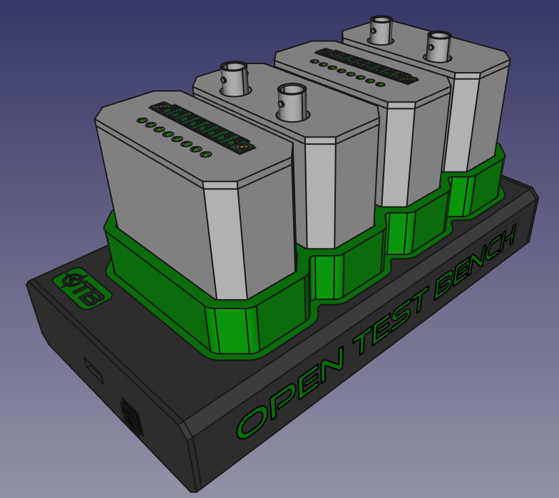
render

Introduction

Open test bench is an open-source platform for drive or characterize any type of system. The system is made for simplifying the development of additional modules called "peripheral module". User connect his computer to backplane unit which gives an access to the peripheral.

Composition
  • Backplane unit.
  • Some peripheral module.
  • Module d'extension (TBD).

Description

Backplane unit

Backplane unit is the main block of the system. It can receive 4 peripherals modules and link user computer to peripheral module. More peripherals modules can be added with the extension module but with slower communication speed.

Backplane unit implement
  • A microcontroller STM32H7.
  • Some channel communication to peripheral modules(SPI 50Mhz, UART 10Mhz, I2C 1Mhz, GPIO).
  • A driver UART <-> USB (FT230H) 12Mb/s.
  • A driver TBD <-> USB ou ETHERNET for high speed communication.
  • Connectors for plug peripheral module.
  • Possibility to add extension module for low-speed peripheral modules.

Peripheral module

Peripheral modules make links with the real world. Each module has an access to 4 communication channels dedicated.

  • SPI with CS
  • UART with RTS/CTS
  • I2C
  • 8 GPIO

Peripheral have an acces to another I2C (I2C_CONTROL) for implement a litle memory (EEPROM) used for calibration data.

Peripheral split

2 connectors is used for a peripheral module, it can be split in two peripherial:

  • Top module have acces to SPI and UART.
  • Bottom module have acces to 8 GPIO and I2C. Each module have an acces to I2C_CONTROL for implement their own EEPROM.
Wide capability
  • Voltage/current measurement.
  • Sensor measurement.
  • Digital input/output.
  • Power management.
  • ....
Suggested format of peripheral module
  • Galvanic isolation for simplifying referenced problems.
  • EEPROM for saves needed calibration.
  • Mechanical dimension (TBD), capability of a double module.

Extension module

Extension module can extend the capabilties of the backplane with lower speed. Each communication channel(UART, I2C, SPI) is multiplexed to each peripheral module. GPIO expander is used for manage the 8 bottom GPIO.

Preliminary definition
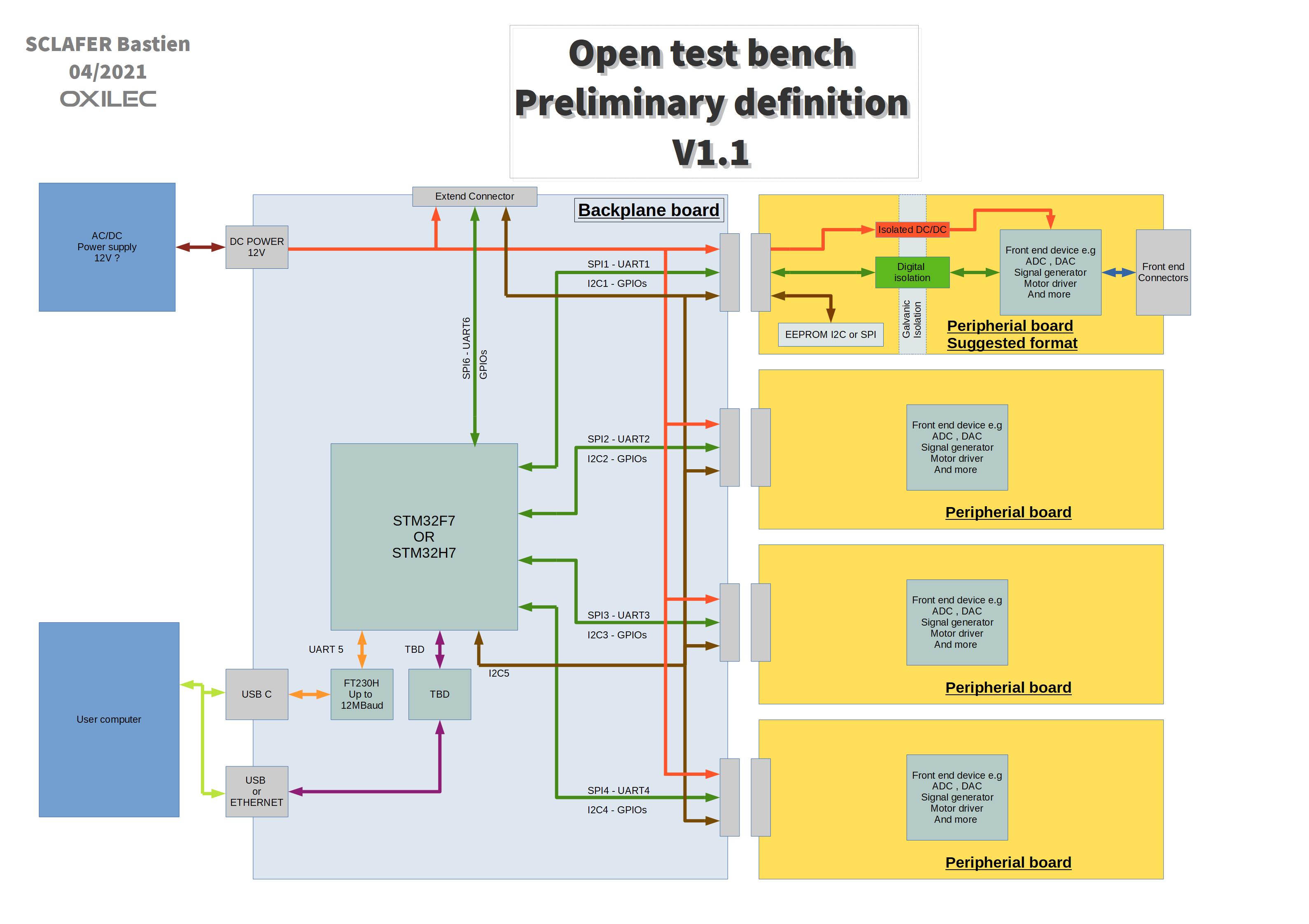
Preliminary definition

Extension definition
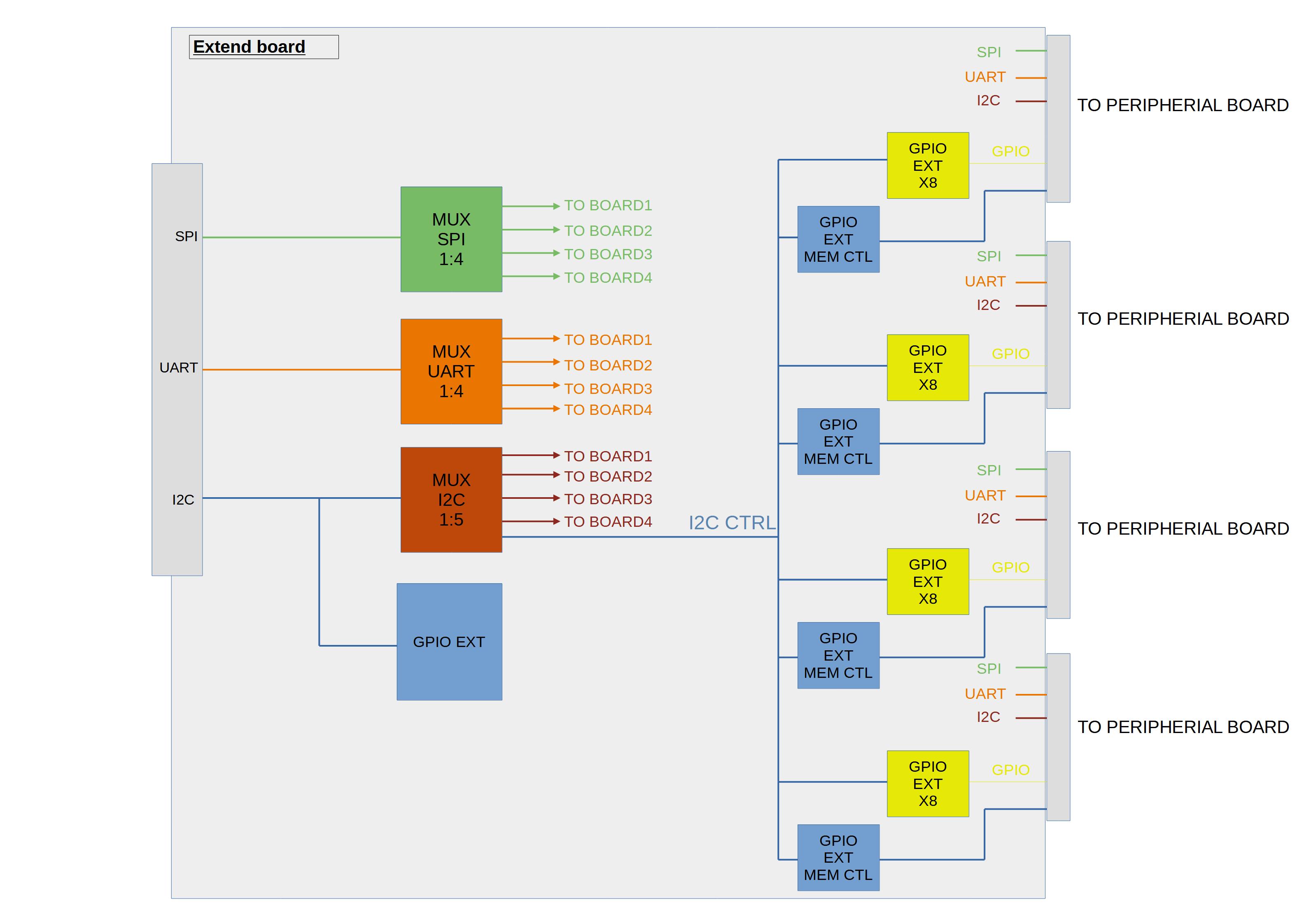
Extension definition

Parts

39
QtyValueFootprintReferences
10CCapacitor_SMD:C_0805_2012MetricC2, C4, C5, C6, C7, C13, C14, C15, C16, C17
8Conn_02x10_Counter_ClockwiseConnector_PinSocket_2.54mm:PinSocket_2x10_P2.54mm_Vertical_SMDJ3, J4, J6, J7, J8, J9, J10, J11
7CP1Capacitor_SMD:CP_Elec_6.3x3C1, C3, C8, C9, C10, C11, C12
4Conn_01x01MountingHole:MountingHole_3.2mm_M3_Pad_ViaJ12, J13, J14, J15
2TJA1021TPackage_SO:SOIC-8_3.9x4.9mm_P1.27mmU4, U5
1Conn_02x20_Counter_ClockwiseConnector_PinSocket_2.54mm:PinSocket_2x20_P2.54mm_HorizontalJ5
1CrystalCrystal:Crystal_SMD_3225-4Pin_3.2x2.5mmY1
1FT230XSPackage_SO:SSOP-16_3.9x4.9mm_P0.635mmU2
1Jack-DCConnector_BarrelJack:BarrelJack_CUI_PJ-102AH_HorizontalJ1
1L7805Package_TO_SOT_SMD:TO-252-2_TabPin1U1
1LOGOMyLibKicad:serigbackG***
1STM32H753ZITxPackage_QFP:LQFP-144_20x20mm_P0.5mmU3
1USB_C_ReceptacleConnector_USB:USB_C_Receptacle_Amphenol_12401548E4-2AJ2

Questions

How big is the Backplane PCB?

It measures 197 × 90 mm and has 2 copper layers, 1.6 mm thick.

What parts does the Backplane use?

39 parts, built around the TJA1021T/10/C, FT230XS-R and L7805. The full list of its parts is on this page, with links to each part's symbol and footprint where PCBKit's library has them.

Where can I download the Backplane KiCad files?

From the bastien313/Open-test-bench repository on GitHub, at the commit this page was made from: the board is 3dvisu/Elec/backplane/backplane.kicad_pcb. PCBKit opens the board in the browser, with nothing to install.

Can I use the Backplane design in my own project?

Its repository publishes it under the GPL-3.0 licence: you may reuse it on that licence's terms (keep the author's notice, and for a copyleft licence share your changes alike).

More from bastien313/Open-test-bench

2
  • 2 layers80 × 66 mmPeriph, the printed circuit board in 3D

    Periph

    bastien313/Open-test-bench

    Open test bench is an open-source platform for drive or characterize any type of system. The system is made for simplifying the development of additional modules called "peripheral module".

    46 parts6GPL-3.0
  • 2 layers80 × 66 mmPeriphAna, the printed circuit board in 3D

    PeriphAna

    bastien313/Open-test-bench

    Open test bench is an open-source platform for drive or characterize any type of system. The system is made for simplifying the development of additional modules called "peripheral module".

    27 parts6GPL-3.0

Similar boards

  • 2 layers100 × 100 mmUsb2most, the printed circuit board in 3D

    Usb2most

    smartgauges/usb2most

    USB to MOST adapter

    139 parts26GPL-3.0
  • 2 layers112 × 57 mmCaravansensor, the printed circuit board in 3D

    Caravansensor

    MartinVerges/womolin-waterlevel

    DIY project to build a smart fuel sensor for RVs or in other projects. It is based on air pressure and is able to measure fresh water as well as grey and black water levels with high precision.

    226 parts17
  • 2 layers43 × 26 mmLIN MFSW Adapter, the printed circuit board in 3D

    LIN MFSW Adapter

    mka1ugin/LIN_MFSW_Adapter

    Аппаратно адаптер выполнен на микроконтроллере STM32F103C8T6, схема и печатная плата разработаны в среде KiCad. Печатная плата односторонняя, габаритные размеры 43 x 26 мм.

    29 parts3
  • 2 layers47.5 × 50 mmJ527, the printed circuit board in 3D

    J527

    mka1ugin/J527

    Дополнительный контроллер для подрулевого блока 5K0953569, реализующий работу кнопки ассистентов, круиза и обогрева руля

    66 parts
  • 2 layers100 × 100 mmEthernet bob base, the printed circuit board in 3D

    Ethernet bob base

    rene-dev/stmbl

    AC Servo Driver for STM32F4

    112 parts990GPL-3.0
  • 2 layers84.4 × 56.8 mmRPi Hat, the printed circuit board in 3D

    RPi Hat

    klaus-liebler/sensact

    Es gibt vier Namespaces für Nachrichten "REQUEST" und "RESPONSE", "EVENT" und "ACKNOWLEDGE". Dies wird mit den beiden LSB des Versions-Namespace-Bytes erklärt (Somit bleiben 64 Versionierungsmöglichkeiten) Alle vier…

    131 parts4Apache-2.0
  • 2 layers229.9 × 111.8 mmAvr colorvideo, the printed circuit board in 3D

    Avr colorvideo

    74hc595/Amethyst

    8-bit ATmega1284 retro computer

    148 parts306BSD-3-Clause
  • 2 layers203.2 × 149.9 mm65C02 Computer, the printed circuit board in 3D

    65C02 Computer

    dbuchwald/6502

    DB6502: 65C02 based computer inspired by BE6502

    68 parts177MIT