2 layers31.6 × 25.2 mm

 barcklay/Cube_SAT
Building Sattelite part time
Hab1 flight is an open-source printed circuit board by barcklay, from the barcklay/Cube_SAT repository on GitHub. It is a 4-layer board of 95.9 × 90.2 mm with 75 parts on 80 nets, routed with 694 tracks and 167 vias.
It is built around the STM32G474RET6, E22-400M22S and LDL1117S33R, with the 1N4148W, AO3400A and AO3401A among its other parts. Its parts include 23 resistors, 15 capacitors, 11 connectors, 3 ICs and 3 diodes. It belongs with the STM32 boards of this library.


The Ebyte E22-400M22S LoRa module has castellated pads at 1.27 mm pitch: it fits neither a breadboard nor jumper wires, and no ready adapter with 2.54 mm pins is sold for it. This small board (31.6 x 25.2 mm, 2 layers) brings every pin out to two rows of ordinary pins 0.8 inch (20.32 mm) apart, so it plugs into a breadboard. It is for the bench and the ground station; the flight board carries the module itself.
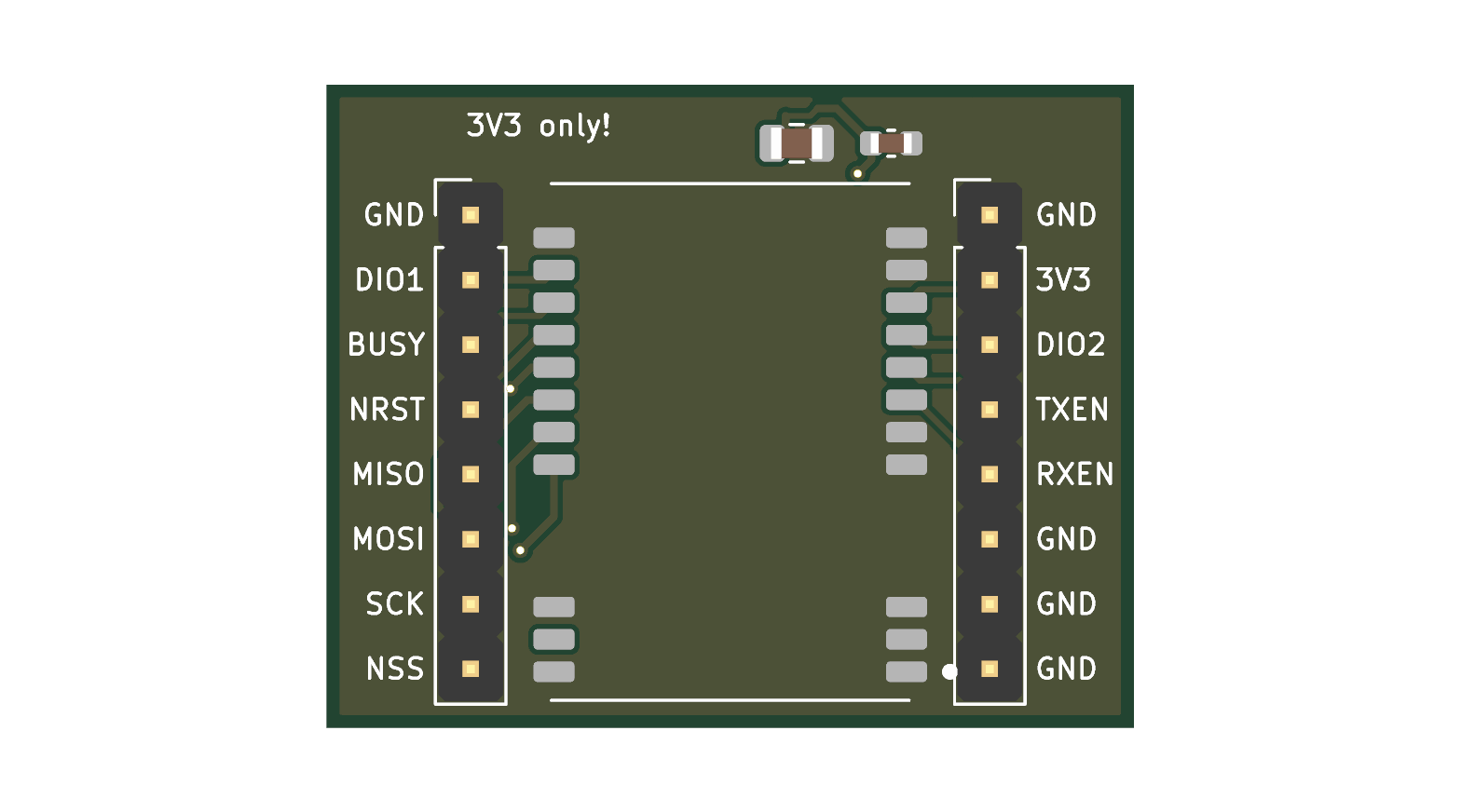
| Left row, top to bottom | Right row, top to bottom |
|---|---|
| GND | GND |
| DIO1 | 3V3 (the module allows 3.7 V at most) |
| BUSY | DIO2 |
| NRST | TXEN |
| MISO | RXEN |
| MOSI | GND |
| SCK | GND |
| NSS | GND |
On the board: the module, 4.7 uF + 100 nF at its supply pin, ground pours on both sides, no tracks under the module on the top side. The antenna goes on the module's own IPX connector.
python3 gen_adapter.py (KiCad's Python) builds everything: e22_adapter.kicad_pcb and, in
fab/, the gerber zip, BOM and CPL for JLCPCB. JLCPCB solders the module (LCSC C411291) and the
two capacitors; the two 1x8 pin rows are soldered by hand, pins pointing down.
Checked: DRC without errors (one cosmetic silkscreen note), 0 unconnected. Not checked: a real order; the rotation of the module in the CPL (look at the placement picture in the order form: the pin-1 dot is at the bottom right, the antenna connector at the bottom left).
| Qty | Value | Footprint | References |
|---|---|---|---|
| 10 | 100n | Capacitor_SMD:C_0603_1608Metric | C4, C5, C6, C7, C8, C9, C12, C13, C15, C16 |
| 8 | 1k | Resistor_SMD:R_0603_1608Metric | R10, R11, R16, R17, R18, R19, R20, R21 |
| 5 | 10k | Resistor_SMD:R_0603_1608Metric | R1, R7, R8, R9, R13 |
| 4 | 4.7k | Resistor_SMD:R_0603_1608Metric | R4, R5, R6, R12 |
| 4 | M3 | MountingHole:MountingHole_3.2mm_M3 | H1, H2, H3, H4 |
| 3 | 100k | Resistor_SMD:R_0603_1608Metric | R2, R22, R23 |
| 2 | 100 | Resistor_SMD:R_0603_1608Metric | R14, R15 |
| 2 | 4.7u | Capacitor_SMD:C_0805_2012Metric | C10, C14 |
| 1 | +3V3 | TestPoint:TestPoint_Pad_D1.5mm | TP1 |
| 1 | 10u | Capacitor_SMD:C_0805_2012Metric | C2 |
| 1 | 10u 16V | Capacitor_SMD:C_0805_2012Metric | C1 |
| 1 | 1N4148W | Diode_SMD:D_SOD-123 | D3 |
| 1 | 1u | Capacitor_SMD:C_0603_1608Metric | C11 |
| 1 | 47k | Resistor_SMD:R_0603_1608Metric | R3 |
| 1 | 600R@100MHz | Inductor_SMD:L_0603_1608Metric | FB1 |
| 1 | ALIVE red | LED_SMD:LED_0603_1608Metric | D1 |
| 1 | AO3400A | Package_TO_SOT_SMD:SOT-23 | Q2 |
| 1 | AO3401A | Package_TO_SOT_SMD:SOT-23 | Q1 |
| 1 | BAROMETER BMP390 | Connector_PinSocket_2.54mm:PinSocket_1x07_P2.54mm_Vertical | J6 |
| 1 | BATTERY 4xL91 | Connector_JST:JST_XH_B2B-XH-A_1x02_P2.50mm_Vertical | J1 |
| 1 | BUZZER (+ / -) | Connector_JST:JST_XH_B2B-XH-A_1x02_P2.50mm_Vertical | J11 |
| 1 | DS18B20 probe | Connector_JST:JST_XH_B3B-XH-A_1x03_P2.50mm_Vertical | J8 |
| 1 | E22-400M22S | hab1:E22-400M22S | U3 |
| 1 | EXPANSION | Connector_PinSocket_2.54mm:PinSocket_1x10_P2.54mm_Vertical | J12 |
| 1 | GND | TestPoint:TestPoint_Pad_D1.5mm | TP2 |
| 1 | GPS FIX yellow | LED_SMD:LED_0603_1608Metric | D2 |
| 1 | GPS MAX-M10S | Connector_PinSocket_2.54mm:PinSocket_1x05_P2.54mm_Vertical | J7 |
| 1 | I2C_SCL | TestPoint:TestPoint_Pad_D1.5mm | TP4 |
| 1 | I2C_SDA | TestPoint:TestPoint_Pad_D1.5mm | TP5 |
| 1 | IMU GY-601N1 | Connector_PinSocket_2.54mm:PinSocket_1x08_P2.54mm_Vertical | J5 |
| 1 | LDL1117S33R | Package_TO_SOT_SMD:SOT-223-3_TabPin2 | U2 |
| 1 | OLED SSD1306 (bench) | Connector_PinSocket_2.54mm:PinSocket_1x04_P2.54mm_Vertical | J10 |
| 1 | POWER SWITCH (on the box) | Connector_JST:JST_XH_B2B-XH-A_1x02_P2.50mm_Vertical | J2 |
| 1 | PTC 0.2A 24V | Fuse:Fuse_1206_3216Metric | F2 |
| 1 | PTC 0.5A 24V | Fuse:Fuse_1206_3216Metric | F1 |
| 1 | RESET | Button_Switch_SMD:SW_SPST_TL3342 | SW1 |
| 1 | SPI FLASH module | Connector_PinSocket_2.54mm:PinSocket_1x06_P2.54mm_Vertical | J4 |
| 1 | SPI1_SCK | TestPoint:TestPoint_Pad_D1.5mm | TP8 |
| 1 | SPI2_SCK | TestPoint:TestPoint_Pad_D1.5mm | TP10 |
| 1 | SPI3_SCK | TestPoint:TestPoint_Pad_D1.5mm | TP9 |
| 1 | STDC14 SWD+VCP | Connector_PinHeader_1.27mm:PinHeader_2x07_P1.27mm_Vertical_SMD | J3 |
| 1 | STM32G474RET6 | Package_QFP:LQFP-64_10x10mm_P0.5mm | U1 |
| 1 | USART1_RX | TestPoint:TestPoint_Pad_D1.5mm | TP7 |
| 1 | USART1_TX | TestPoint:TestPoint_Pad_D1.5mm | TP6 |
| 1 | VBAT_PROT | TestPoint:TestPoint_Pad_D1.5mm | TP3 |

etiennechlt/electronic-chess
Générée par tools/boardgen (module power). 100 x 60 mm, 2 couches, plan de masse en face arrière. Elle gère trois cellules plates 1S 5 Ah.

hoeken/frothfet
Yarrboard load controller board with current sense, volt sense, fuses, and sender support.

JuanPoueriet/automatic-spork
Máquina de ruleta física de casino. 6 PCBs: pic32main (cerebro), wheel (rueda de LEDs), displaysa/b/c (paneles de 7 segmentos en cascada) y buttons (botonera).

FeruzTopalov/spoke
Standalone LoRa-based real-time off-grid relative GPS navigation for group of up to 5 people. Improved version of LRNS Eleph

Boardoza/Boardoza_E22-900M22S_Long_Range_LoRa_Breakout_Board
Long-range LoRa® breakout board based on the Ebyte E22-900M22S and Semtech SX1262 transceiver.

PTR-projects/PTR_mega_hardware
Welcome to the KPPTR-hardware repository! This repository contains the design files for the hardware components used in the KPPTR project.


It measures 95.9 × 90.2 mm and has 4 copper layers, 1.6 mm thick.
75 parts, built around the STM32G474RET6, E22-400M22S, LDL1117S33R and 1N4148W. The full list of its parts is on this page, with links to each part's symbol and footprint where PCBKit's library has them.
From the barcklay/Cube_SAT repository on GitHub, at the commit this page was made from: the board is hardware/flight_pcb/hab1_flight.kicad_pcb and its schematic hardware/flight_pcb/hab1_flight.kicad_sch. PCBKit opens the board in the browser, with nothing to install.
Its repository states no licence, so its author keeps all rights: ask barcklay before reusing the design.