
4 layers36.4 × 15 mm
Ovrdrive
o7-machinehum/phantomdrive
Seemingly normal USB drive with a hidden security feature
57 parts1kMIT

 barbeque/ardscsino-fork1
Fork of the ArdSCSIno to use my own board design
Dirty ardscsino is an open-source printed circuit board by barbeque, from the barbeque/ardscsino-fork repository on GitHub. It is a 2-layer board of 70.9 × 82 mm with 21 parts on 50 nets, routed with 310 tracks and 70 vias.
It is built around the DM3AT-SF-PEJM5. Its parts include 3 diodes, 3 connectors, 2 capacitors, 2 ICs and 1 resistor. It belongs with the STM32 boards of this library.
Dirty ArdSCSIno II, V1 board works on at least one system using the BlueSCSI v1 USB firmware. Please refer to the table below for full testing.
| Platform | Works? | Comments |
|---|---|---|
| Macintosh LC | Yes | With termination power |
Warning: these instructions are a work in progress. Please report any hangups (that aren't related to crappy Blue Pills, see below) so we can fix this section.
I have used the BlueSCSI Updater project to flash these, but you can also use the QMK Toolbox project which basically runs the same commands.
You will need an STLink-V2 programmer (eBay clones are fine) and at least four jumper wires. I recommend doing this before you solder the Blue Pill to the board.
For the boards without jumpers (i.e. the USB-C ones that I warn about lower down - go take a look) you can do the following steps instead:
| Position | Component | Digi-Key part number | Comments |
|---|---|---|---|
| C1 | 4.7µF through-hole capacitor | ||
| C2 | 0.1µF 0805 SMD ceramic capacitor | ||
| D1 | Optional activity LED, 3mm radial | ||
| J1 | 50-pin SCSI box header, male | 3M157291-ND | |
| J2 | 4-pin Berg floppy power, TE 171825-4 | A106197-ND | |
| J3 | micro SD card slot, Hirose DM3AT-SF-PEJM5 | HR1964CT-ND | |
| U2 | STM32 Blue Pill C8T6 | This should be sourced from AliExpress; see below for common problems. | |
| R1 | 560Ω through-hole resistor | ||
| RN1, RN4 | 10-pin (9-way) bussed 220Ω resistor network | 4610X-1-221LF-ND | |
| RN2, RN3 | 10-pin (9-way) bussed 330Ω resistor network | 4610X-1-331LF-ND |
Because the STM32 Blue Pill has been knocked off by a jillion different individuals, here are some of the problems I've encountered while trying to build these boards.
You might want to try the Blue Pill Diagnostics project. Again, it's a good idea to run this before you solder your microcontroller down. It really sucks to desolder it after! Ask me how I know.
On many Blue Pills sold today, pin 40 is a "5V" pin. My board expects this pin to be ground. If you try to bring it up without modification, it will short the +5V power supply to ground and probably cause something unpleasant to happen.
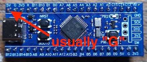
The best thing to do here is to simply not solder this pin to the board: I do a 20-pin male header on one side and a 19-pin male header on the other side.
Please notice also that the LED pin on this board is changed from normal; BlueSCSI firmware will expect it at PC13 and this one is at PB2.
Make sure you are getting a STM32...C8T6 board. These have enough flash for the BlueSCSI firmware. Otherwise, you can get a mysterious LIBUSB_ERROR_TIMEOUT (C6T6) and nothing will work.
The Blue Pill Diagnostics should report that you have at least 64kB of regular flash and at least 64kB of "hidden" flash. A C6 has only 32kB.
| Qty | Value | Footprint | References |
|---|---|---|---|
| 2 | 1n5818 | Diode_THT:D_DO-41_SOD81_P7.62mm_Horizontal | D2, D3 |
| 2 | 220Ω | Resistor_THT:R_Array_SIP10 | RN1, RN4 |
| 2 | 330Ω | Resistor_THT:R_Array_SIP10 | RN2, RN3 |
| 2 | Jumper_2_Bridged | Jumper:SolderJumper-2_P1.3mm_Bridged_RoundedPad1.0x1.5mm | JP4, JP5 |
| 2 | Jumper_2_Small_Bridged | Jumper:SolderJumper-2_P1.3mm_Bridged_RoundedPad1.0x1.5mm | JP2, JP3 |
| 1 | 0.1µF | Capacitor_SMD:C_0805_2012Metric_Pad1.18x1.45mm_HandSolder | C2 |
| 1 | 10µF | Capacitor_THT:CP_Radial_D5.0mm_P2.00mm | C1 |
| 1 | 171825-4 (Ext. Power) | 171825-4:TE_171825-4 | J2 |
| 1 | 560Ω | Resistor_THT:R_Axial_DIN0207_L6.3mm_D2.5mm_P10.16mm_Horizontal | R1 |
| 1 | DM3AT-SF-PEJM5 | sd-card:HRS_DM3AT-SF-PEJM5 | J3 |
| 1 | Ext. Activity | LED_THT:LED_D3.0mm | D1 |
| 1 | SCSI | Connector_PinHeader_2.54mm:PinHeader_2x25_P2.54mm_Horizontal | J1 |
| 1 | STM32 Bluepill | blue-pill-kicad-master:blue_pill | U1 |
| 1 | microSD-Breakout | microSD_Breakout:microSD_AliExpress | U2 |
The 19 most common of 21 parts.
It measures 70.9 × 82 mm and has 2 copper layers, 1.6 mm thick.
21 parts, built around the DM3AT-SF-PEJM5. The full list of its parts is on this page, with links to each part's symbol and footprint where PCBKit's library has them.
From the barbeque/ardscsino-fork repository on GitHub, at the commit this page was made from: the board is dirty-ardscsino.kicad_pcb and its schematic dirty-ardscsino.kicad_sch. PCBKit opens the board in the browser, with nothing to install.
Its repository states no licence, so its author keeps all rights: ask barbeque before reusing the design.
o7-machinehum/phantomdrive
Seemingly normal USB drive with a hidden security feature

o7-machinehum/flipper-blackhat
Linux based WiFi pentesting device for the Flipper Zero.


antmicro/snapdragon-845-baseboard
https://antmicro.com/blog/2022/04/open-source-snapdragon-845-baseboard/


newaetech/sonata-pcb
Design files and associated documentation for Sonata PCB, part of the Sunburst Project

Fabmicro-LLC/Karnix_ASB-254
Karnaugh Interactive Extendable ASIC Simulation Board AKA Karnix ASB-254