2 layers77.5 × 118 mm

 BackSlasher/breezy
My AC controller
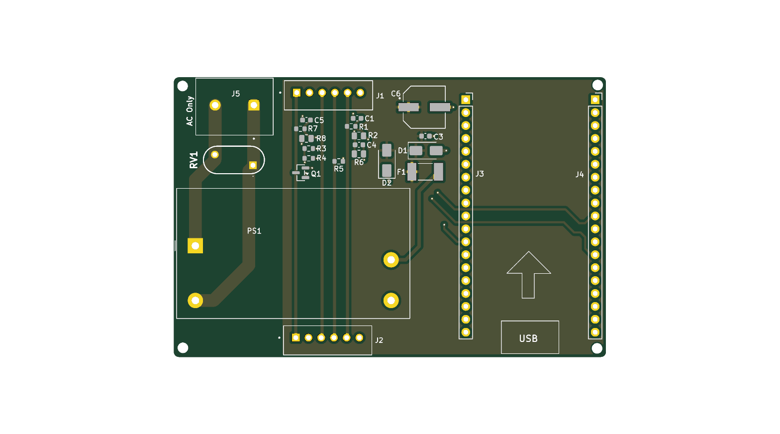
Breezy Redesign is an open-source printed circuit board by BackSlasher, from the BackSlasher/breezy repository on GitHub, published under the MIT licence. It is a 2-layer board of 85 × 55 mm with 29 parts on 47 nets, routed with 141 tracks and 20 vias.
It is built around the IRM-10-5, 0ZCG0200AF2B and B72210S0321K551, with the EEEFK1E101P, MMBT2222A and SMAJ5.0A among its other parts. Its parts include 8 resistors, 5 capacitors, 5 connectors, 2 diodes and 1 transistor.


ESP32 smart-home component for my air conditioner, physically sitting between the HVAC controller and its LCD control panel.
The kit here is a USP 5010 — controller plus LCD panel (the panel is marked USP5010BE). If that is what you have, the protocol docs and the ESPHome components in this repo should work as-is.
Smart-home capability achieved with ESPHome (flashed via USB, OTA available).
Reads are done by intercepting SPI updates from the AC to the panel.
Writes are done by emulating IR remote commands.
Physical wiring:
JST wiring is 5v (5v+, gnd, SPI data, SPI clock, IR)
The ESP32 itself is a socketed 38-pin ESP32-WROOM-32 DevKitC-style module (2×19 headers) — not included on the PCB, plug in your own.
The HVAC and its panel talk over a clocked two-wire bus, ~33 ms per cycle. There are exactly two frames on it:
Every bit of the controller status is located and its encoding known, so a
frame can be generated from scratch and checked against the two checksums it
carries. Two flag bits are still unexplained — I know where they are and
when they fire, just not what they mean; one is probably the panel's
backlight. Full field map in docs/PROTOCOL_BUS.md.
The controller is receiving IR commands from a remote via the LCD panel. The panel holds an IR receiver, demodulates the output and sends the binary on a dedicated wire to the controller, which we can both intercept and send our own.
The IR protocol is reverse engineered completely: any mode, temperature and
fan speed can be composed from scratch, including power-on, which carries the
target state inside the toggle so the unit wakes straight into it. Full spec
in docs/PROTOCOL_IR.md.
Two things about it are worth knowing before you read anything else:
Bus pirate worked out of the box for reading, and Arduino R4 bitbanging was enough for writing.
When moving to dedicated ESP32+PCB, I had to iterate a bit.
My main pain points were:
A recurring pattern was that ESP32 was not a reliable narrator when it had other duties.
I had several mysteries caused by the ESP32 doing something else (IR transmission, verbose logging) that occupied it enough so it missed bits, generating corrupt or odd frames, both making understanding current state much harder.
If the measurement is weird, use a dedicated device (another esp32, BusPirate etc)
This board is powered directly from 220 V AC through screw terminals on the PCB. It is a hobby project, not a certified appliance — it has had no safety testing or approval of any kind. In particular, note it has no mains-side fuse: F1 is a resettable PTC on the 5 V output, and the varistor sits unfused across L–N. If you build one, you are responsible for knowing how to work safely with mains, for enclosing it properly, and for whatever your local regulations require. Don't work on it energised.
MIT — see LICENSE.
| Qty | Value | Footprint | References |
|---|---|---|---|
| 3 | 100k | Resistor_SMD:R_0603_1608Metric | R1, R5, R7 |
| 3 | 100pF | Capacitor_SMD:C_0603_1608Metric | C1, C4, C5 |
| 3 | 180k | Resistor_SMD:R_0805_2012Metric | R2, R6, R8 |
| 2 | B6B-XH-A_LF__SN_ | B6B_XH_A:JST_B6B-XH-A_LF__SN_ | J1, J2 |
| 2 | Conn_01x19_Socket | Connector_PinSocket_2.54mm:PinSocket_1x19_P2.54mm_Vertical | J3, J4 |
| 1 | 0ZCG0200AF2B | 0ZCG0200AF2B:FUSER_0ZCG0200AF2B | F1 |
| 1 | 10 KΩ | Resistor_SMD:R_0603_1608Metric | R4 |
| 1 | 100nF | Capacitor_SMD:C_0603_1608Metric | C3 |
| 1 | 1731721 | 1731721:PHOENIX_1731721 | J5 |
| 1 | 1KΩ | Resistor_SMD:R_0603_1608Metric | R3 |
| 1 | B72210S0321K551 | B72210S0321K551:B72210S0321K551 | RV1 |
| 1 | EEEFK1E101P | EEEFK1E101P:CAP_EEEFK1E101P | C6 |
| 1 | IRM-10-5 | Converter_ACDC:Converter_ACDC_MeanWell_IRM-10-xx_THT | PS1 |
| 1 | LOGO | Bree:bree_Final | G*** |
| 1 | MMBT2222A | Package_TO_SOT_SMD:SOT-23 | Q1 |
| 1 | SMAJ5.0A | Diode_SMD:D_SMA | D1 |
| 1 | SS14 | Diode_SMD:D_SMA | D2 |
The 25 most common of 29 parts.
It measures 85 × 55 mm and has 2 copper layers, 1.6 mm thick.
29 parts, built around the IRM-10-5, 0ZCG0200AF2B, B72210S0321K551 and EEEFK1E101P. The full list of its parts is on this page, with links to each part's symbol and footprint where PCBKit's library has them.
From the BackSlasher/breezy repository on GitHub, at the commit this page was made from: the board is pcb/breezy_v4/Breezy _ Redesign.kicad_pcb and its schematic pcb/breezy_v4/Breezy _ Redesign.kicad_sch. PCBKit opens the board in the browser, with nothing to install.
Its repository publishes it under the MIT licence: you may reuse it on that licence's terms (keep the author's notice, and for a copyleft licence share your changes alike).

hicancan/carbentra-smart-plug
CARBENTRA smart plug: AIoT edge device for campus energy orchestration

z1ntus/VRC-CB-Digital-Heating-Controller
Digital replacement controller for the Vaillant VRC-CB heating controller.

jasperhax0r/CompaqPortableKeyboard
Mechanical Keyboard for the original Compaq Portable XT-Class

rico-x/GemilaiMate
Gemilai 3007Z DIY carrier and standalone firmware. Prototype: hardware not assembled or tested.


Doantheodoisuckhoe/Thietbitheodoisuckhoe
Bản 1.3 (30/10/2026). Mạch 2 lớp 50 × 62 mm ghép các module có sẵn, toàn bộ linh kiện hàn tay được (điện trở, tụ 0805; SOT-23; SOD-323; SMA; header 2,54 mm).

Turboblider55/Project_OpenGauge
Modular Vehicle Telemetry and Infotainment Companion via OBD-II