8 layers280 × 195 mm
 azonenberg/starshipraider193
Open hardware test equipment
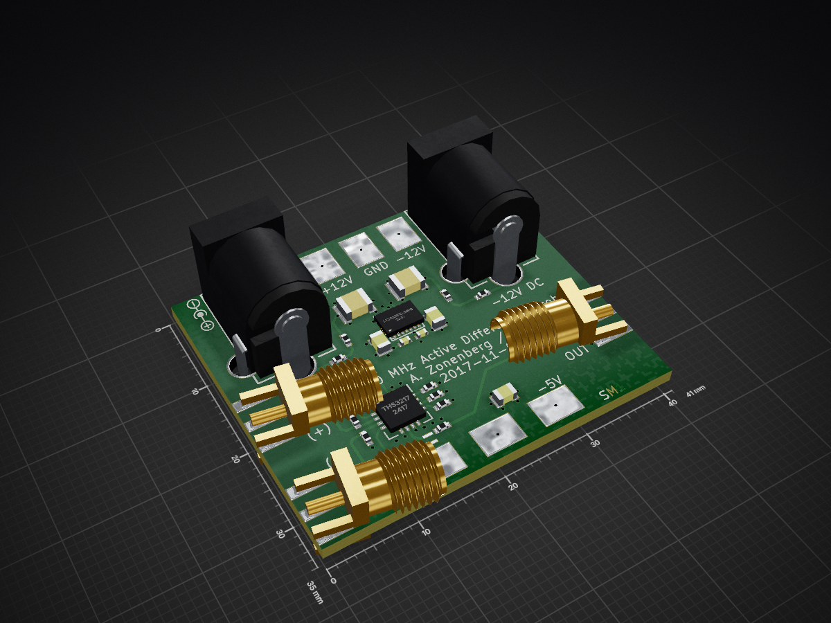
Diffprobe prototype is an open-source printed circuit board by azonenberg, from the azonenberg/starshipraider repository on GitHub, published under the BSD-3-Clause licence. It is a 4-layer board of 41 × 35 mm with 49 parts on 26 nets, routed with 412 tracks and 95 vias.
It is built around the AT0603T06ECATD and LT3032IDE-5#PBF. Its parts include 14 capacitors, 11 connectors, 10 resistors, 2 ICs and 2 switches.


This is the umbrella repo for a lot of my T&M projects. Some will end up in separate repos.
Boards, subsystems, etc are all named after famous electrical engineers who made major contributions to the field of test equipment design.
All instruments are planned to share the same basic platform. Generally speaking, this platform will be:
Trigger Crossbar
Currently in progress. Not planning to make in volume, focus is on prototyping as much of the platform as possible to speed development and de-risk future projects. Prototype assembled, firmware dev in progress.
kup-lulz: One-off Kintex UltraScale+ test board on OSHPark 4 layers, using a sketchy reballed aliexpress FPGA. Intended as a low-risk validation for UltraScale+ based power, pcb footprint/schematic, and some RTL development. Schematic complete, fine tuning layout.
GROVER: Kintex UltraScale+ based 10/25G BERT. On hold until kup-lulz is brought up and working as it will essentially be a scaled-up version of the same design
VOLLUM (Howard Vollum, co-inventor of triggered-sweep oscilloscope)
All are 8 channels??
BLONDEL (Andre-Eugene Blondel, inventor of electromechanical oscillograph)
8 bit: 100 MHz / 250 - 500 - 1000 Msps
12 bit: 50 MHz / 125 - 250 - 500 Msps
4 AFE : 1 HMCAD1520
Two acquisition cards, 4 channels each
One XC7A100T-2FGG676 on main board
One DDR3 800 SODIMM on main board
DUDDELL (William Duddell, inventor of moving-coil mirror oscillograph)
250 MHz / 1 Gsps, 1 AFE : 1 HMCAD1520
1x XC7K160T-2FFG676
Eight analog cards, one HMCAD1520 + one AFE each One digital card with 1-2 SFF-8087 connectors for LA One AWG card with a TBD JESD204 DAC using unused serdes lanes (assuming 4 for 40G, one for 10G, three available)
ZENNECK (Jonathan Zenneck, inventor of electrically scanned CRT oscilloscope)
500 MHz or 1 GHz / 5 Gsps, 1 AFE : 1 AD9213-6G
Per channel:
Global:
VOLLUM (Howard Vollum, co-inventor of triggered-sweep oscilloscope)
1-2 GHz / 10 Gsps, 1 AFE : 1 AD9213
MURDOCK (Melvin Jack Murdock, co-inventor of triggered-sweep oscilloscope)
6 GHz / 40 Gsps, 1 AFE : 4 AD9213
CONWAY (VLSI pioneer, co-author of Mead & Conway)
8-bit comparator-to-LVDS logic analyzer pod with SFF-8087 interface and high-impedance inputs
MEAD (other half of Mead & Conway)
8-bit comparator-to-LVDS logic analyzer pod with SFF-8087 interface and 50 ohm inputs
MAXWELL (James Clerk Maxwell, discovered Maxwell's Equations)
Kintex-7 ISERDESE2 based LA
TODO: Artix-7 GTP based LA??
DENNARD (Robert Dennard, inventor of DRAM)
Kintex-7 GTX based LA
BRAUN (Karl Ferdinand Braun, inventor of optically scanned CRT oscilloscope and phased array) Low-bandwidth active probe ADA4817-1ACPZ-R7
FLEMING (John Ambrose Fleming, inventor of vacuum tube) 4 channel 14 bit 2.5 Gsps arbitrary waveform generator, AD9739 + Kintex-7 + DDR3 SODIMM based. Need ~160 Gbps of RAM bandwidth to keep them fed
Two channels of 14-bit LVDS per DAC = 28 LVDS pairs for data, assume clock/sync are external to FPGA Slow control: 4 wire SPI, IRQ = 5 slow lines
4x DAC = 84 pairs (168 pins used / 4 banks / 200 allocated) + 15 slow lines
Two xc7k160t's, two dacs + 1 sodimm of ram on each
4GB DDR3 SODIMM, 1 GB per channel = 512 Mpoints of waveform data Probably some digital outputs (mix of LVDS and LVCMOS, and maybe some slow pin headers?)
| Qty | Value | Footprint | References |
|---|---|---|---|
| 6 | TESTCLIP | azonenberg_pcb:TESTPOINT_SMT_KEYSTONE_5016 | P5, P6, P7, P8, P9, P10 |
| 4 | 0.01 uF | azonenberg_pcb:EIA_0402_CAP_NOSILK | C5, C6, C13, C14 |
| 4 | 0.47 uF | azonenberg_pcb:EIA_0402_CAP_NOSILK | C3, C4, C7, C8 |
| 4 | 4.7 uF 10V | azonenberg_pcb:EIA_0805_CAP_NOSILK | C1, C2, C11, C12 |
| 4 | DNP | azonenberg_pcb:EIA_0402_RES_NOSILK | R3, R4, R5, R6 |
| 3 | 49.9 | azonenberg_pcb:EIA_0402_RES_NOSILK | R1, R2, R9 |
| 3 | SMA | azonenberg_pcb:CONN_SMA_EDGE_SAMTEC_SMA_J_P_H_ST_EM1 | P1, P2, P11 |
| 2 | 0 | azonenberg_pcb:EIA_0402_RES_NOSILK | R7, R8 |
| 2 | 10 uF 25V | azonenberg_pcb:EIA_1210_CAP_NOSILK | C9, C10 |
| 2 | 250 mA | azonenberg_pcb:EIA_0402_RES_NOSILK | F1, F2 |
| 2 | BLM15PX471SN1D | azonenberg_pcb:EIA_0402_RES_NOSILK | L1, L2 |
| 2 | CUI PJ-058BH | azonenberg_pcb:CONN_CUI_PJ-058BH_HIPWR_BARREL_NOSLOT | K1, K2 |
| 2 | TESTPOINT | azonenberg_pcb:TESTPOINT_BARETRACE_328UM | P3, P4 |
| 1 | AT0603T06ECATD | azonenberg_pcb:ATC_AT_0603 | R10 |
| 1 | LOGO | w_logo:Logo_silk_OSHW_6x6mm | G*** |
| 1 | LOGO | w_logo:Logo_silk_polarity_center_5x1.4mm | G*** |
| 1 | LOGO | w_logo:Logo_silk_WEEE_3.4x5mm | G*** |
| 1 | LOGO | w_logo:Logo_silk_ROHS_5x2.8mm | G*** |
| 1 | LOGO | w_logo:Logo_silk_polarity_external_5x1.4mm | G*** |
| 1 | LOGO | azonenberg_pcb:LONGTHING-1200DPI | G*** |
| 1 | LT3032IDE-5#PBF | azonenberg_pcb:DFN_14_0.5MM_4x3MM_DUALPAD_LTC_DE14MA | U1 |
| 1 | THS3217 | azonenberg_pcb:QFN_16_0.65MM_4x4MM | U2 |
It measures 41 × 35 mm and has 4 copper layers, 1.6 mm thick.
49 parts, built around the AT0603T06ECATD and LT3032IDE-5#PBF. The full list of its parts is on this page, with links to each part's symbol and footprint where PCBKit's library has them.
From the azonenberg/starshipraider repository on GitHub, at the commit this page was made from: the board is boards/old-prototypes/diffprobe-prototype/diffprobe-prototype.kicad_pcb. PCBKit opens the board in the browser, with nothing to install.
Its repository publishes it under the BSD-3-Clause licence: you may reuse it on that licence's terms (keep the author's notice, and for a copyleft licence share your changes alike).


azonenberg/starshipraider
Open hardware test equipment


azonenberg/starshipraider
Open hardware test equipment

azonenberg/starshipraider
Open hardware test equipment


hackclub/OnBoard
💡 Join 1,000 teenagers and make your first PCB with a $100 grant!


AndreiVladescu/ESP32-Bit-Pirate-Hardware
Carrier breaker-board for the ESP32-S3 Devkit. Works great with the ESP32-Bit-Pirate firmware.


h0lad/SolarMeshtasticNode
This is a Meshtastic Solar Node PCB based on the Heltec HT-CT62 and the linear solar charge controller TI BQ25185.
