
2 layers40 × 40 mm

 azasypkin/kroneum47
🕒 -.- .-. --- -. . ..- -- Kroneum -.- .-. --- -. . ..- -- 🕒
Kroneum is an open-source printed circuit board by azasypkin, from the azasypkin/kroneum repository on GitHub, published under the MIT licence. It is a 2-layer board of 30 × 30 mm with 31 parts on 24 nets, routed with 212 tracks and 18 vias.
It is built around the BAT54C. Its parts include 7 capacitors, 4 switches, 2 resistors, 2 ICs and 1 diode. It belongs with the robots and motor control boards and the STM32 boards of this library.

Disclaimer: I needed a dumb, autonomous, configurable and GUI-less physical timer to better manage my own time during the day and that is how Kroneum was born. Another goal was to see how well Rust fits into embedded development (basic interactions with MCU, USB stack and I2C driver).
Kroneum is an experimental, accessible (no GUI) and fully open source (both in code and hardware) time tracker device.
There is neither GUI/LCD nor Wi-Fi/Bluetooth interface available, just two buttons one can use to configure the timer. More advanced users can use built-in USB functionality to configure device (via dedicated CLI tool with optional Web interface), upgrade firmware (via DFU interface) or upload various Krouneum "recipes" (e.g. to repurpose device completely).
By default device stays in a standby low power mode and wakes up as soon as any of the button is being pressed for 3-5 seconds. As mentioned above there are just two buttons: Ⅰ (Roman one) and Ⅹ (Roman ten).
StandBy mode - device enters into Setup modeSetup mode - increases desired timer by one unitSetup mode - increases desired timer by ten unitsSetup mode - sets timer treating unit as a second (see example below)Setup mode - sets timer treating unit as a minute (see example below)Setup mode - sets timer treating unit as an hour (see example below)Alarm mode - resets current alarm if any and enters Setup modeAlarm mode - resets current alarm if any and enters StandBy modeConfiguration mode and powers up USB interfaceOnce timer fires up it will be repeated every 10 seconds (configurable) until it's acknowledged by the long press on both Ⅰ and Ⅹ.
5s timer5m timer5h timer21s timer10m timerAdvanced users can configure device via USB with the help of dedicated CLI tool, assuming device is in Configuration mode and
connected to the host PC via micro USB cable:
$ cargo run -- info

$ cargo run -- beep -n5

$ cargo run -- alarm get
$ cargo run -- alarm set "5m 15s"

$ cargo run -- flash read 0x1f
$ cargo run -- flash write 0x1f 10
$ cargo run -- flash erase

$ cargo run -- reset
It's also possible to use CLI tool as a standalone server with a minimalistic Web interface:
$ cargo run -- ui
  Running Kroneum Web UI on http://127.0.0.1:8080
Web server is bound to a local http://127.0.0.1:8080 address and can be accessed with any modern browser:
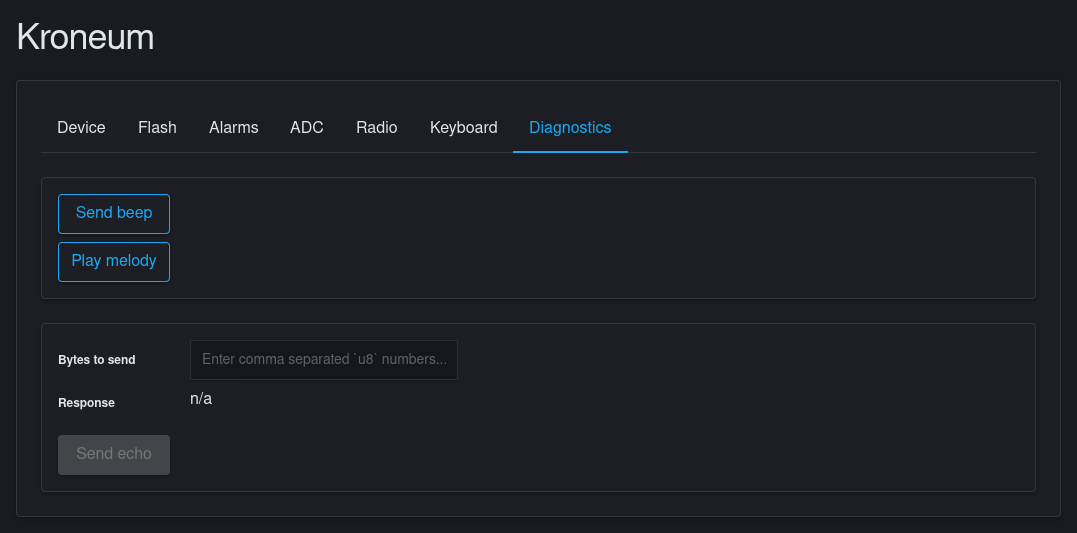
Run cargo run -- help for more details.
NOTE: To use CLI tool without root privilege you may need to add the following udev rule:
/etc/udev/rules.d/50-kroneum.rules
----------
SUBSYSTEMS=="usb", ATTRS{idVendor}=="1209", ATTRS{idProduct}=="deed", GROUP="users", MODE="0660"
And then manually force udev to trigger this rule:
# udevadm triggerIn the future releases Web interface will be using WebHID API completely eliminating the need in the local Web server.
If you feel adventurous you can easily build and flash custom firmware to Kroneum. You can use ./scripts/flash.sh script
from fw folder to build and flash default firmware or few custom examples:
Default firmware:
# Default firmware
$ ./scripts/flash.sh

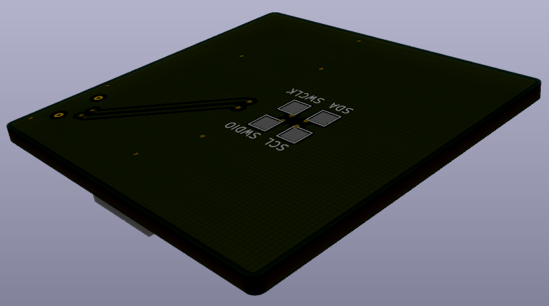
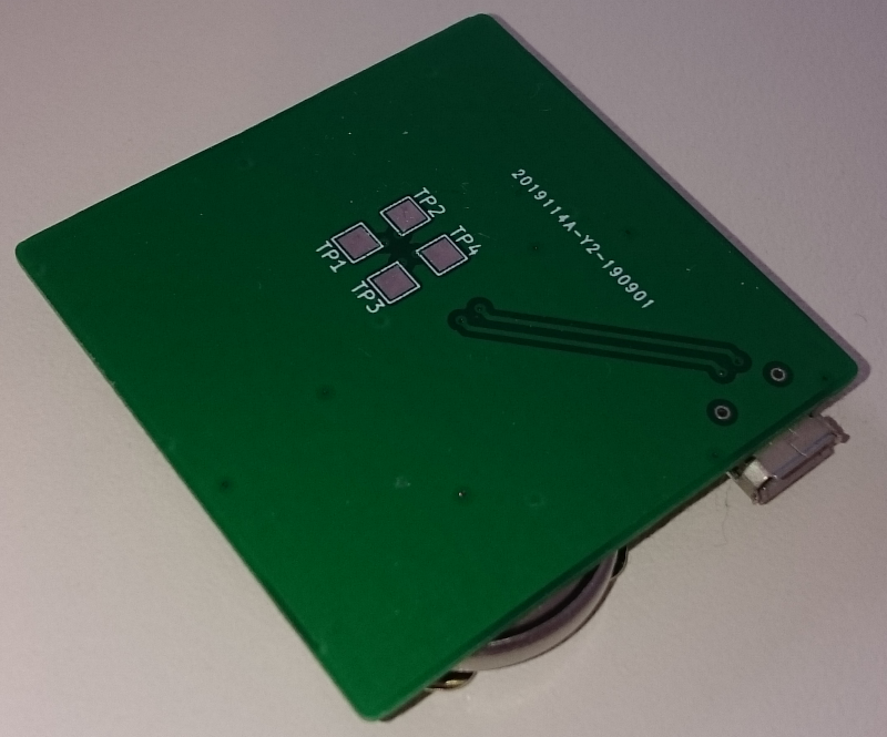
# Example: blinking through TP1/SDA pad exposed on the back side of Kroneum PCB
$ ./scripts/flash.sh blinky

# Example: interfacing with SSD1306 LCD via TP1/SDA and TP2/SCL pads exposed on the back side of Kroneum PCB
$ ./scripts/flash.sh i2c_ssd1306
The flash.sh script is essentially consequent calls of cargo build --release ..., cargo objcopy --release ... and dfu-util ....
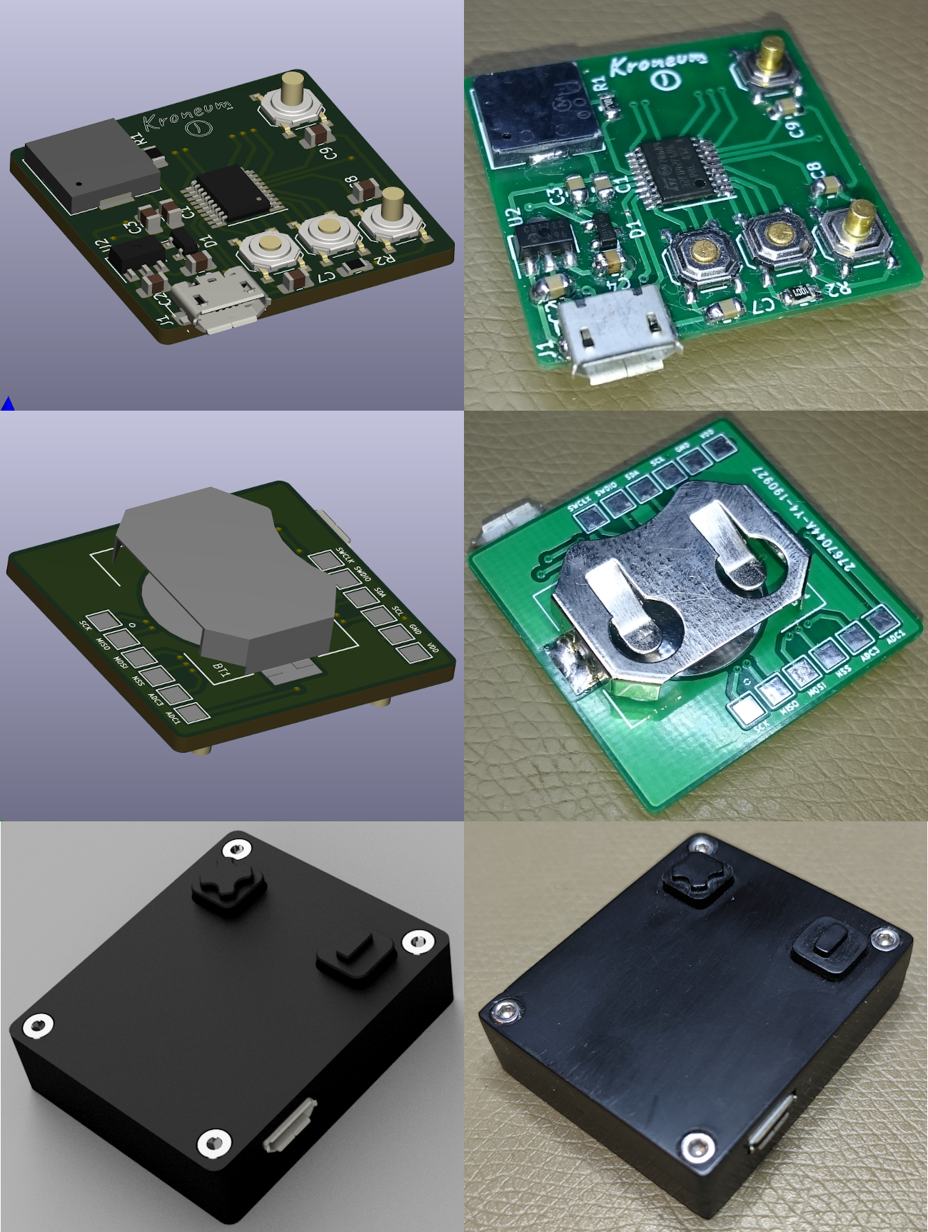
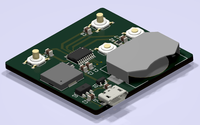
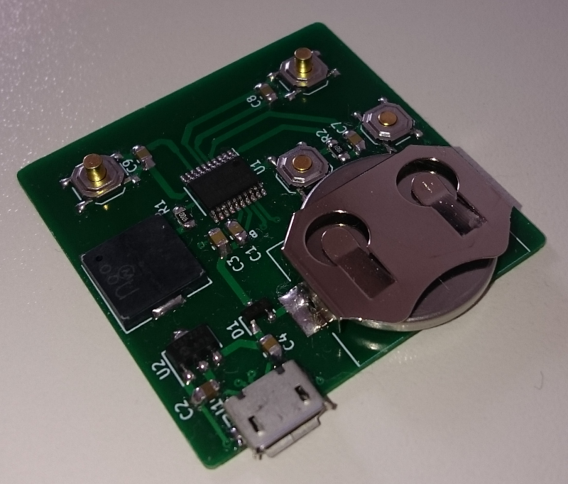
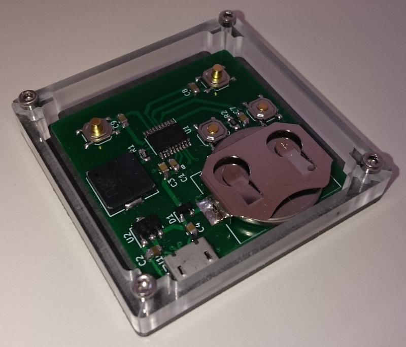
Schematics is done in KiCad and can be found here. PCB includes SWD, I2C and CR2032 connectors and may look a bit
oversized because of that, but on the bright side hand soldering and CNC engraving was a breeze.
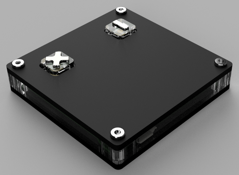
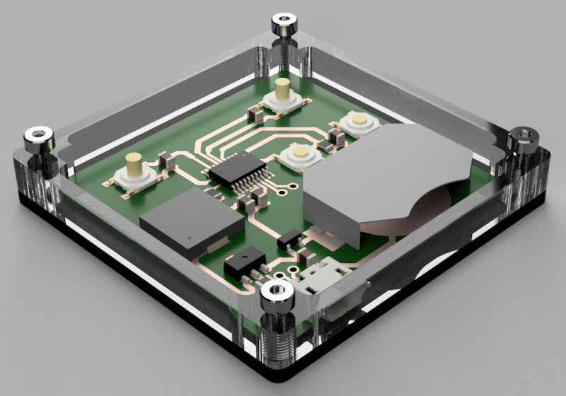
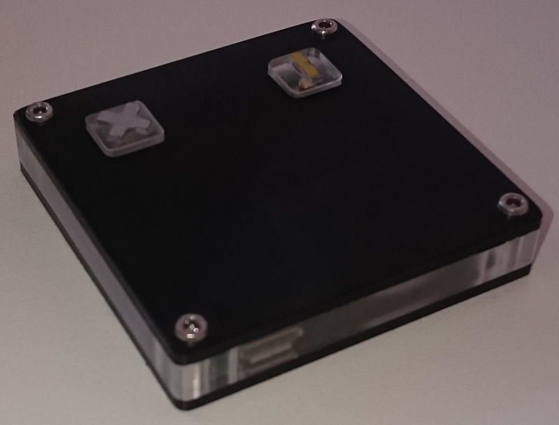
The most recent enclosure was machined from 5mm (base and cap) and 2mm (buttons) Delrin and the older versions were machined from 5mm Plexiglas (walls and buttons) and 2mm Delrin (base and cap). G-Code can be found here.
See PCB and enclosure renders and photos of how it turned in real:
-.- .-. --- -. . ..- --
| Qty | Value | Footprint | References |
|---|---|---|---|
| 12 | Peripherals | TestPoint:TestPoint_THTPad_2.0x2.0mm_Drill1.0mm | ADC1, ADC3, GND, MISO, MOSI, NSS, SCK, SCL, SDA, SWCLK, SWDIO, VDD |
| 4 | 0.1u | Capacitor_SMD:C_0805_2012Metric_Pad1.15x1.40mm_HandSolder | C1, C7, C8, C9 |
| 2 | 1u | Capacitor_SMD:C_0805_2012Metric_Pad1.15x1.40mm_HandSolder | C2, C4 |
| 1 | 1M | Resistor_SMD:R_0805_2012Metric_Pad1.15x1.40mm_HandSolder | R2 |
| 1 | 4.7u | Capacitor_SMD:C_0805_2012Metric_Pad1.15x1.40mm_HandSolder | C3 |
| 1 | 470 | Resistor_SMD:R_0805_2012Metric_Pad1.15x1.40mm_HandSolder | R1 |
| 1 | BAT54C | Package_TO_SOT_SMD:SOT-23 | D1 |
| 1 | Battery | LINX_BAT-HLD-001:LINX_BAT-HLD-001_0 | BT1 |
| 1 | Boot_Mode_Btn | tl3342:tl3342 | SW1 |
| 1 | Buzzer | Buzzer_Murata_PKMCS0909E4000-R1:Buzzer_Murata_PKMCS0909E4000-R1 | BZ1 |
| 1 | Ctrl_One_Btn | tl3342:tl3342 | SW2 |
| 1 | Ctrl_Ten_Btn | tl3342:tl3342 | SW4 |
| 1 | MCP1700-3302E_SOT89 | Package_TO_SOT_SMD:SOT-89-3 | U2 |
| 1 | Reset_Btn | tl3342:tl3342 | SW3 |
| 1 | STM32F042F4Px | tssop-20x6.5mmx4:TSSOP-20_4.4x6.5mm_P0.65mm | U1 |
| 1 | USB_B_Micro | micro_usb:USB_Micro-B_Molex-105017-0001 | J1 |


theta-machines/DEV-G2-NANO
The G2 Nano is powered by a record-breaking 1 GHz Arm Cortex-M7 processor, combining the performance of an application processor with real-time determinism.

Duet3D/Duet-2-Hardware
The KiCAD source for the Duet 3d printer controller see www.duet3d.com


jkramarz/TheTick
The Tick is the next evolution in covert access control system implants for simulating adversary-in-the-middle attacks.
M17-Project/Module_17
M17 modem board for 9600-baud capable radios

It measures 30 × 30 mm and has 2 copper layers, 1.6 mm thick.
31 parts, built around the BAT54C. The full list of its parts is on this page, with links to each part's symbol and footprint where PCBKit's library has them.
From the azasypkin/kroneum repository on GitHub, at the commit this page was made from: the board is hw/pcb/Rev_0.6/kroneum.kicad_pcb. PCBKit opens the board in the browser, with nothing to install.
Its repository publishes it under the MIT licence: you may reuse it on that licence's terms (keep the author's notice, and for a copyleft licence share your changes alike).