
2 layers327.9 × 139 mm
Coco2
baldengineer/bit-preserve
Project for capturing vintage, classic, aka old computer schematics in KiCad.
147 parts446

 AYUSH-pro-grammer/led-timer
LED chase ("blinky") circuit created for beginners in Stasis.
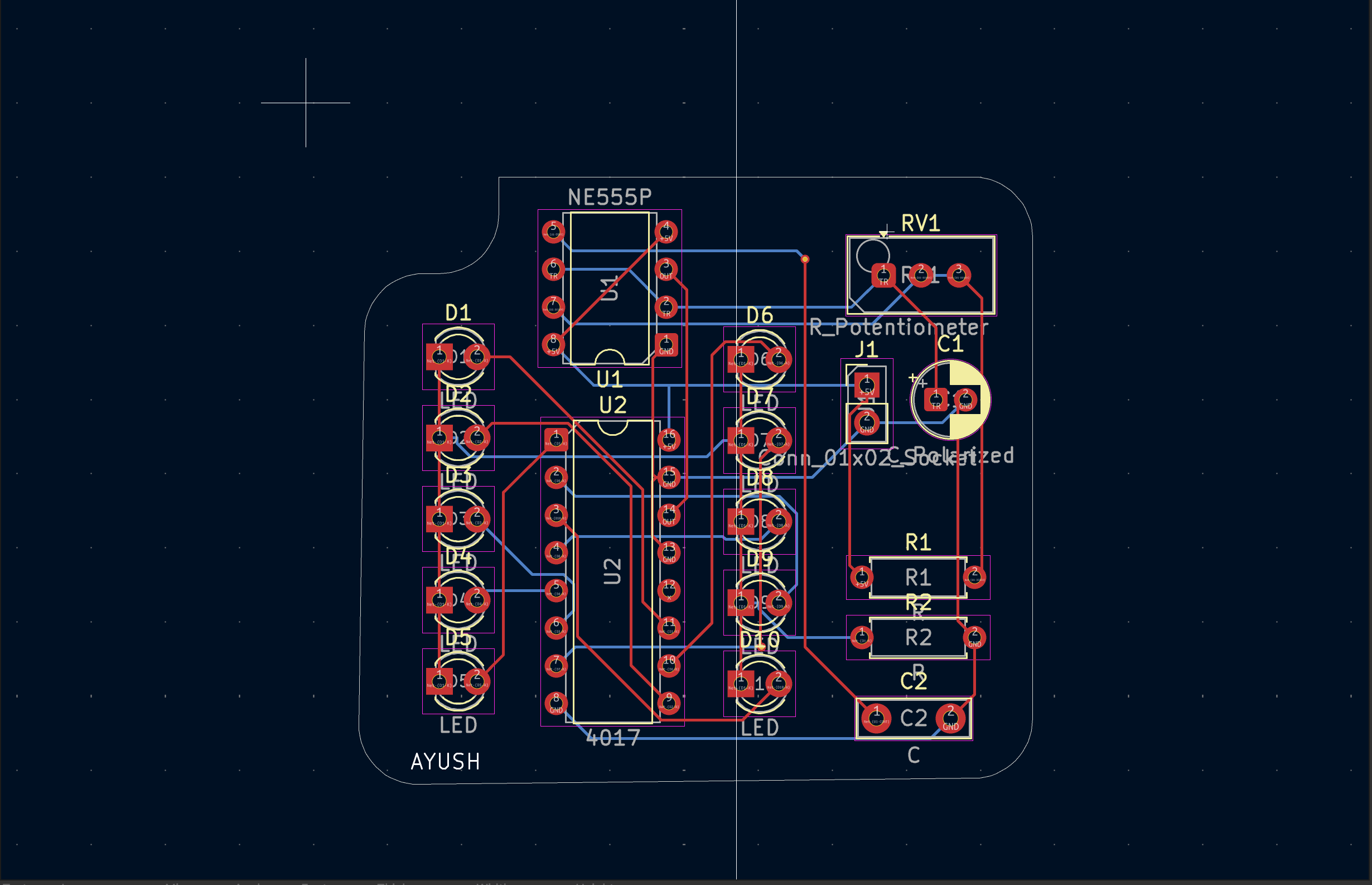
StarLight is an open-source printed circuit board by AYUSH-pro-grammer, from the AYUSH-pro-grammer/led-timer repository on GitHub. It is a 2-layer board of 45.4 × 41 mm with 18 parts on 18 nets, routed with 113 tracks and 2 vias.
It is built around the NE555P. Its parts include 10 diodes, 2 capacitors, 2 resistors, 2 ICs and 1 connector.
LED chase ("blinky") circuit created for beginners in Stasis.
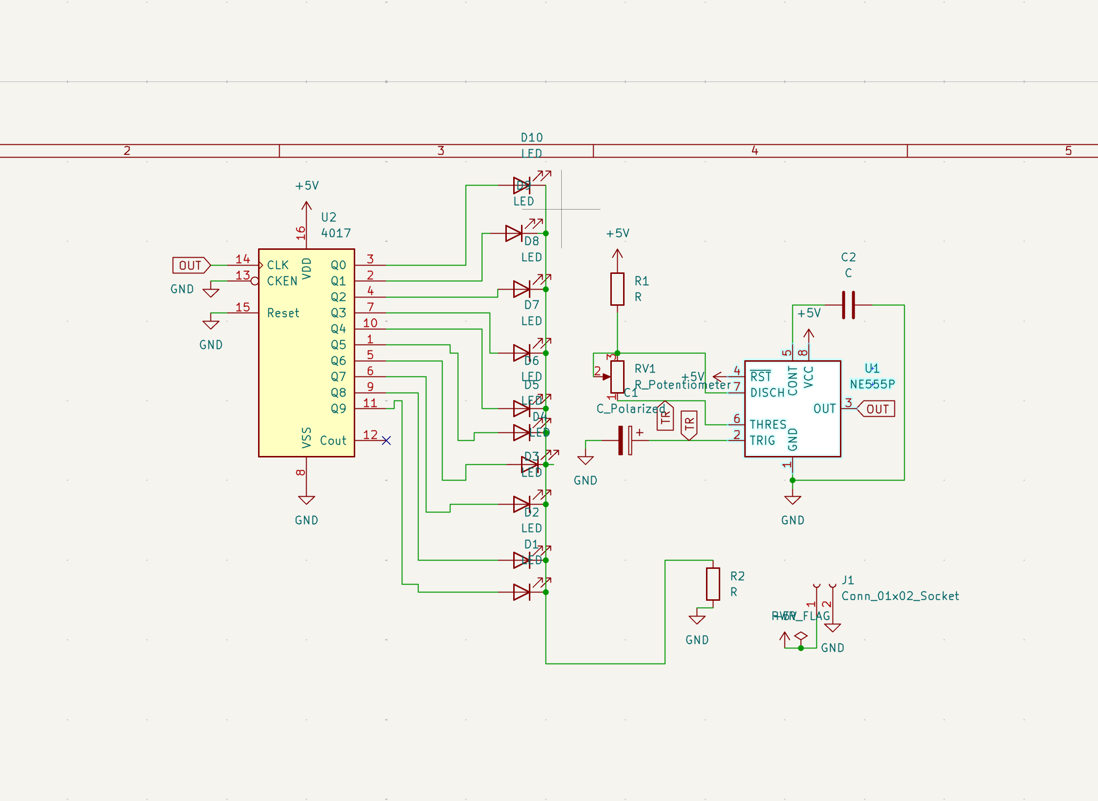
NE555 timer as a pulse generator CD4017 decade counter to control outputs Several LEDs as indicators
Pulses generated by the 555 timer trigger the 4017, which switches LEDs to form a running light.
Speed control using potentiometer Easy and newbie-friendly design Use of popular parts Perfect for digital & analog electronics basics education
.
├── bom.csv              # Bill of materials
├── grb 2.zip            # Gerber files for PCB manufacturing
├── image/
│   ├── schematic.png    # Circuit diagram
│   ├── pcb.png          # PCB layout
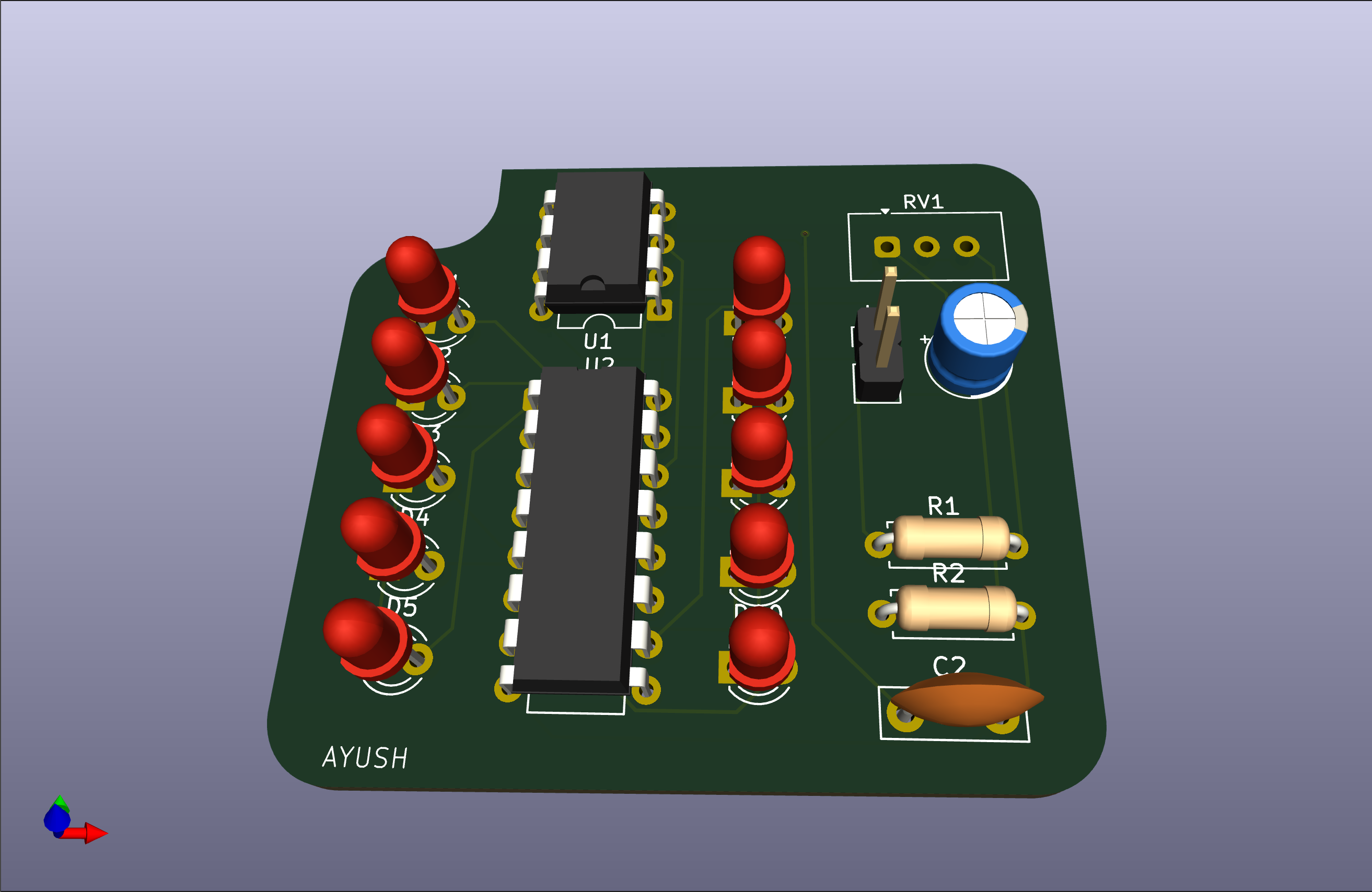
│   └── 3d.png           # 3D view
├── kicad/
│   ├── StarLight.kicad_sch
│   ├── StarLight.kicad_pcb
│   └── StarLight.kicad_pro
└── README.mdbom.csvimage/schematic.png
image/pcb.png
image/3d.png
Developed as a basic hardware project
| Qty | Value | Footprint | References |
|---|---|---|---|
| 10 | LED | LED_THT:LED_D3.0mm | D1, D2, D3, D4, D5, D6, D7, D8, D9, D10 |
| 2 | R | Resistor_THT:R_Axial_DIN0207_L6.3mm_D2.5mm_P7.62mm_Horizontal | R1, R2 |
| 1 | 4017 | Package_DIP:DIP-16_W7.62mm | U2 |
| 1 | C | Capacitor_THT:C_Disc_D7.5mm_W2.5mm_P5.00mm | C2 |
| 1 | C_Polarized | Capacitor_THT:CP_Radial_D5.0mm_P2.00mm | C1 |
| 1 | Conn_01x02_Socket | Connector_PinHeader_2.54mm:PinHeader_1x02_P2.54mm_Vertical | J1 |
| 1 | NE555P | Package_DIP:DIP-8_W7.62mm | U1 |
| 1 | R_Potentiometer | Potentiometer_THT:Potentiometer_Vishay_T93YA_Vertical | RV1 |
It measures 45.4 × 41 mm and has 2 copper layers, 1.6 mm thick.
18 parts, built around the NE555P. The full list of its parts is on this page, with links to each part's symbol and footprint where PCBKit's library has them.
From the AYUSH-pro-grammer/led-timer repository on GitHub, at the commit this page was made from: the board is kicad /StarLight.kicad_pcb and its schematic kicad /StarLight.kicad_sch. PCBKit opens the board in the browser, with nothing to install.
Its repository states no licence, so its author keeps all rights: ask AYUSH-pro-grammer before reusing the design.
baldengineer/bit-preserve
Project for capturing vintage, classic, aka old computer schematics in KiCad.

The-Invent0r/8-bit-Computer-PCB
These are the KiCAD files for my 8-Bit Computer.

DarcyJProjects/touchtone555
An open-source DIY, NE555-based analogue synthesizer - play notes with a stylus


benjiaomodular/SynthCard
I designed this project with the help of PCBWay. You can get a copy of these cards through the PCBWay Shared Projects page.

fortinsylvain/MyCpu
Home brew CPU Hardware with 1-bit ALU implementation using 74LSxx, a micro-code and assembler coded in C#.

hackup/C128Diag
Replica of the Commodore C128 Diagnostic Test cartridge Assy No. 325093-01.