
4 layers120 × 113 mm
Voron Klipper Board
VoronDesign/Voron-Hardware
Cool Hardware designed by the Voron Design group
360 parts1.1kGPL-3.0

 awonak/synthcard16
Synth Card for Adam Wonak
Sc awonak is an open-source printed circuit board by awonak, from the awonak/synthcard repository on GitHub, published under the GPL-3.0 licence. It is a 2-layer board of 88.6 × 50.6 mm with 45 parts on 44 nets, routed with 189 tracks and 4 vias.
It is built around the BAT43. Its parts include 14 resistors, 7 diodes, 6 capacitors and 6 connectors.
Synth Card for Adam Wonak
This synthcard is a circuit inspired by Hagiwo's SyncLFO and Bezier Curve, and the Modulove MVMNT. I chose this design because of the seemingly endless creative firmware scripts I have written for the Modulove Sync LFO, so I wanted to make a business card to highlight this circuit design with some fun tweaks.
This is an iteration of the SynthCard.com community from Benjie Jiao.
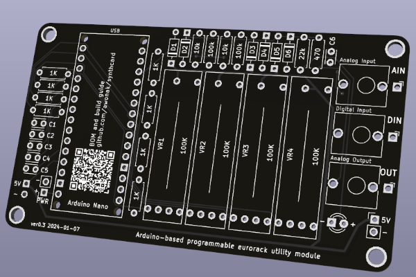
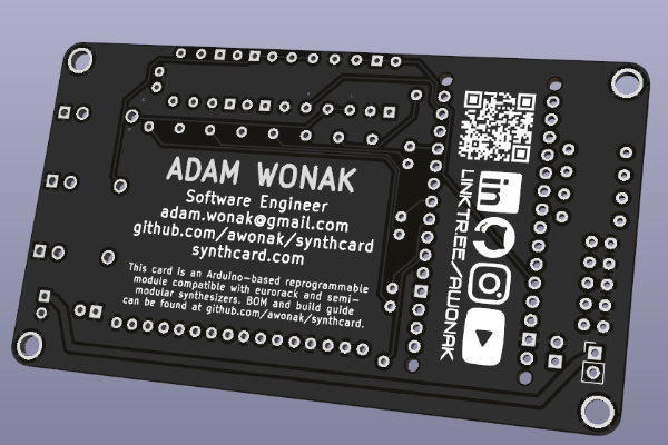
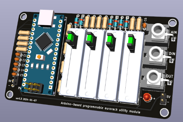
4 Step Sequencer - https://youtu.be/5_vGYVA8IQ8
ADSR - https://youtu.be/wfQtB7HLKf4
[@benjiaomodular] - https://youtube.com/shorts/xnUs8CACG_8
[@bildpunkt] - https://youtu.be/3e_gjm9oc40
To assist with assembly, you can use the interactive ibom.html page to view a part placement guide.
| Arduino Pin | Function |
|---|---|
| A0 | Slider 1 Input |
| A1 | Slider 2 Input |
| A2 | Slider 3 Input |
| A3 | Slider 4 Input |
| A7 | Analog Input |
| D3 | Slider 4 LED |
| D5 | Slider 3 LED |
| D6 | Slider 2 LED |
| D9 | Slider 1 LED |
| D10 | Digital Output |
| D11 | Digital Input |
The most basic program we can write for the Synth Card is a Blink program. Using the pin guide above, we can see the digital output is D10 which has an LED connected to the circuit. We can use this pin to blink the LED.
#define CV_OUT 10  // CV Output with LED

void setup() {
  pinMode(CV_OUT, OUTPUT);
}

void loop() {
  digitalWrite(CV_OUT, HIGH);
  delay(500);
  digitalWrite(CV_OUT, LOW);
  delay(500);
}
To test out all of the inputs, outputs, and LEDs, you can flash the HardwareTest script.
To see additional example firmware scripts, head over to firmware.
| Revision | Date | Notes |
|---|---|---|
| ver0.3 | 2024-01-07 | - Change: minor silkscreen updates - Change: made 5v trace larger |
| ver0.2 | 2023-12-28 | - Fix: CV Output circuit was backwards - Change: Rename capacitor footprint values - Change: Improved LED footprint values - Change: Add linktr.ee and social logos |
| ver0.1 | 2023-12-18 | Initial release |

| Qty | Value | Footprint | References |
|---|---|---|---|
| 8 | 1K | Resistor_THT:R_Axial_DIN0207_L6.3mm_D2.5mm_P7.62mm_Horizontal | R1, R2, R3, R4, R11, R12, R13, R14 |
| 6 | BAT43 | Diode_THT:D_DO-35_SOD27_P7.62mm_Horizontal | D1, D2, D3, D4, D5, D6 |
| 5 | 0.1uF | Capacitor_THT:C_Disc_D3.0mm_W2.0mm_P2.50mm | C1, C2, C3, C4, C5 |
| 4 | 100K | PCM_4ms_Potentiometer:Pot_Slider_LED_20mm_RA2045F | VR1, VR2, VR3, VR4 |
| 4 | MountingHole_Pad | MountingHole:MountingHole_3.2mm_M3_Pad | H1, H2, H3, H4 |
| 2 | 100k | Resistor_THT:R_Axial_DIN0207_L6.3mm_D2.5mm_P7.62mm_Horizontal | R6, R8 |
| 2 | 10k | Resistor_THT:R_Axial_DIN0207_L6.3mm_D2.5mm_P7.62mm_Horizontal | R5, R7 |
| 2 | Conn_01x02 | Connector_PinHeader_2.54mm:PinHeader_1x02_P2.54mm_Vertical | J4, J5 |
| 1 | 22k | Resistor_THT:R_Axial_DIN0207_L6.3mm_D2.5mm_P7.62mm_Horizontal | R9 |
| 1 | 4.7uF | Capacitor_THT:C_Disc_D3.0mm_W2.0mm_P2.50mm | C6 |
| 1 | 470 | Resistor_THT:R_Axial_DIN0207_L6.3mm_D2.5mm_P7.62mm_Horizontal | R10 |
| 1 | Analog Input | Connector_Audio:Jack_3.5mm_QingPu_WQP-PJ398SM_Vertical_CircularHoles | J1 |
| 1 | Analog Output | Connector_Audio:Jack_3.5mm_QingPu_WQP-PJ398SM_Vertical_CircularHoles | J3 |
| 1 | Arduino Nano | PCM_arduino-library:Arduino_Nano_Socket | A1 |
| 1 | Conn_01x02 | Connector_PinSocket_2.54mm:PinSocket_1x02_P2.54mm_Vertical | J6 |
| 1 | Digital Input | Connector_Audio:Jack_3.5mm_QingPu_WQP-PJ398SM_Vertical_CircularHoles | J2 |
| 1 | LED | LED_THT:LED_D3.0mm | D7 |
| 1 | LOGO | Demo:socials | G*** |
| 1 | LOGO | Demo:qr2 | G*** |
| 1 | LOGO | Demo:qr | G*** |
It measures 88.6 × 50.6 mm and has 2 copper layers, 1.6 mm thick.
45 parts, built around the BAT43. The full list of its parts is on this page, with links to each part's symbol and footprint where PCBKit's library has them.
From the awonak/synthcard repository on GitHub, at the commit this page was made from: the board is hardware/sc_awonak.kicad_pcb and its schematic hardware/sc_awonak.kicad_sch. PCBKit opens the board in the browser, with nothing to install.
Its repository publishes it under the GPL-3.0 licence: you may reuse it on that licence's terms (keep the author's notice, and for a copyleft licence share your changes alike).
VoronDesign/Voron-Hardware
Cool Hardware designed by the Voron Design group


ravinrabbid/DonCon2040
RP2040 based firmware and hardware for DIY Taiko no Tatsujin Drum Controllers

Testbild-synth/HAGIWO_arduino_oscillator
4HP through hole version of the HAGIWO FM/additive/chord oscillator with mode switch and gain input.

Testbild-synth/Hagiwo_009_030_sequencer
A through-hole PCB conversion of HAGIWO's 6 channel eurorack gate sequencer. Includes Gerbers, Code and building instructions.

bvarner/pi485
An open-source TTL UART <-> RS485 converter, intended for a Raspberry Pi or Arduino

Testbild-synth/HAGIWO-029-033-Eurorack-quantizer
Through hole PCB version of the HAGIWO Dual Quantizer/SH101 Sequencer Eurorack Module-.