

4 layers24.4 × 24.4 mm
OSO SWAT C1-rounded
joeycastillo/Sensor-Watch
A board replacement for the classic Casio F-91W wristwatch
36 parts2.1k
The diagram below shows how all onboard subsystems connect to the ESP32-S3:
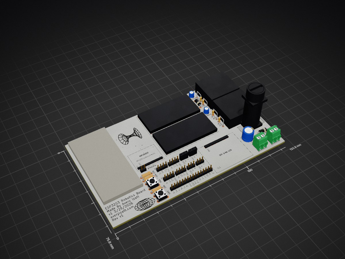
Tank is an open-source printed circuit board by averyizatt, from the averyizatt/ESP32BasedRobiticsPCB repository on GitHub, published under the MIT licence. It is a 4-layer board of 133.8 × 75.6 mm with 36 parts on 57 nets, routed with 432 tracks and 20 vias.
Its parts include 2 ICs, 2 diodes, 2 switches and 1 fuse.




A professional-grade, 4-layer ESP32-S3 robotics controller PCB that consolidates motor control, multi-axis sensing, and user interaction into a single, scalable platform.
| PCB Layout (Top) | 3D Render | PCB Back |
|---|---|---|
The diagram below shows how all onboard subsystems connect to the ESP32-S3:
                        ┌─────────────────────────────────────┐
                        │           ESP32-S3-WROOM-1           │
                        │     240 MHz Xtensa LX7 Dual-Core     │
                        │     WiFi 802.11 b/g/n  •  BT 5.0    │
                        └───┬───┬───┬───┬───┬───┬───┬───┬─────┘
                            │   │   │   │   │   │   │   │
          ┌─────────────────┘   │   │   │   │   │   │   └──────────────────┐
          │ LEDC PWM            │   │   │   │   │   │ GPIO ISR             │
          ▼                     │   │   │   │   │   ▼                      │
 ┌─────────────────┐            │   │   │   │   │  ┌────────────────┐      │
 │   DRV8871 ×2    │            │   │   │   │   │  │  Hall Sensors  │      │
 │  DC Motor Ctrl  │            │   │   │   │   │  │   ×2 inputs    │      │
 │  (PWM IN1/IN2)  │            │   │   │   │   │  └────────────────┘      │
 └────────┬────────┘            │   │   │   │   │                          │
          │ VM (motor power)    │   │   │   │   │ INPUT_PULLUP             │
          ▼                     │   │   │   │   ▼                          │
    ┌───────────┐               │   │   │   │  ┌──────────────┐            │
    │  Motor ×2 │               │   │   │   │  │  Buttons ×2  │            │
    └───────────┘               │   │   │   │  └──────────────┘            │
                      PWM 50Hz  │   │   │   │                              │
                                ▼   │   │   │ SPI                          │
                       ┌────────────┐  │   ▼                               │
                       │  Servo 1   │  │  ┌──────────────────┐             │
└────────────┘ │ │ SPI Display │ │| Subsystem | Component | Capability |
|---|---|---|
| Microcontroller | ESP32-S3-WROOM-1 | 240 MHz dual-core, WiFi, BT 5.0, 45 GPIOs |
| Motor Drivers | 2× DRV8871 | H-bridge, 3.6 A peak, bidirectional DC control |
| Servo Outputs | 1 active channel | Servo 1 on GPIO 8; GPIO 9 is used by the menu potentiometer |
| Ultrasonic Sensors | 4× HC-SR04 | 2–400 cm range, 15° beam angle |
| Hall Effect Sensors | 2× inputs | Wheel speed, pulse counting, position feedback |
| IMU | I2C header | MPU-6050, ICM-42688, or any I2C IMU |
| SPI Display | ST7735S 160×80 | TFT_eSPI driver, tabbed on-device UI |
| Push Buttons | 2× SMD tactile | Top = enter/select, bottom = back/stop; debounced in firmware |
| Expansion | GPIO header | GPIO 40, 43, 44, and shared GPIO 48 available for expansion |
| Power | LDO + distribution | Onboard 3.3 V regulation, motor VM bus |
| WiFi AP | Soft Access Point | SSID RoboController, live sensor dashboard |
| Web Dashboard | AsyncWebSocket | Tabbed UI: sensors, WiFi scan, BLE radar, drive control |
| Remote Control | WebSocket JSON | Browser joystick → motor drive; Servo 1 slider |
| BLE GATT Server | NimBLE-Arduino | Sensor notify + motor/servo write characteristics |
| BLE Scanner | Passive scan | Detect nearby BLE devices, shown on TFT and dashboard |
The board uses a 4-layer stackup (1.6 mm total thickness) to provide dedicated power and ground planes, minimizing noise and improving signal integrity:
  ┌─────────────────────────────────────────────┐  ← Component side
  │  Layer 1 — F.Cu (Top)                        │  Signal routing + high-current motor traces
  ├─────────────────────────────────────────────┤
  │  Prepreg                                     │
  ├─────────────────────────────────────────────┤
  │  Layer 2 — In1.Cu                            │  Solid GND plane (unbroken)
  ├─────────────────────────────────────────────┤
  │  Core                                        │
  ├─────────────────────────────────────────────┤
  │  Layer 3 — In2.Cu                            │  VM + 3.3 V power distribution
  ├─────────────────────────────────────────────┤
  │  Prepreg                                     │
  ├─────────────────────────────────────────────┤
  │  Layer 4 — B.Cu (Bottom)                     │  Additional signals + local copper pours
└─────────────────────────────────────────────┘ ← Solder side| Layer | Role | Trace Width |
|---|---|---|
| F.Cu (Top) | Signal routing + high-current motor paths | 0.2 mm signal / 2.0 mm motor VM |
| In1.Cu | Solid GND reference plane | — |
| In2.Cu | VM + 3.3 V power distribution | 0.8 mm+ |
| B.Cu (Bottom) | Additional signals + local copper pours | 0.2 mm signal |
Design decisions to ensure reliable operation in a noisy motor-drive environment:
| Reference | Part | Package | Description |
|---|---|---|---|
| U1 | ESP32-S3-WROOM-1 | SMD module | Main MCU — 240 MHz, WiFi, BT 5.0 |
| U2 | DRV8871 | HSOP-8 | Motor driver — Motor 1 |
| U3 | DRV8871 | HSOP-8 | Motor driver — Motor 2 |
| U4 | 3.3 V LDO | SOT-223 | 3.3 V regulated power for MCU and logic |
| J1–J4 | HC-SR04 headers | 4-pin 2.54 mm | Ultrasonic sensor connectors |
| J5–J6 | Hall sensor headers | 3-pin 2.54 mm | Hall effect sensor connectors |
| J7–J8 | Motor terminals | 2-pin screw terminal | Motor output connections |
| J9 | Expansion header | 8-pin 2.54 mm | Breakout for unused GPIO |
| J10 | Display header | 7-pin 2.54 mm | SPI display connector |
| SW1–SW2 | Tactile switches | SMD | User input buttons used by current firmware |
Full BOM with part numbers and quantities is available in
hardware/bom/.
| GPIO | Function | Type | Notes |
|---|---|---|---|
| 1 | Hall Sensor 1 | Digital Input | Interrupt-driven pulse counting |
| 2 | Hall Sensor 2 | Digital Input | Interrupt-driven pulse counting |
| 4 | Motor 1 PWM A | LEDC Output | 20 kHz PWM, 8-bit resolution |
| 5 | Motor 1 PWM B | LEDC Output | 20 kHz PWM, 8-bit resolution |
| 6 | Motor 2 PWM A | LEDC Output | 20 kHz PWM, 8-bit resolution |
| 7 | Motor 2 PWM B | LEDC Output | 20 kHz PWM, 8-bit resolution |
| 8 | Servo 1 | PWM Output | 50 Hz via ESP32Servo library |
| 9 | Potentiometer | ADC Input | Main menu scroll / analog control; Servo 2 disabled in firmware |
| 10 | Ultrasonic 1 TRIG | Digital Output | 10 µs trigger pulse |
| 11 | Ultrasonic 1 ECHO | Digital Input | Pulse width → distance |
| 12 | Ultrasonic 2 TRIG | Digital Output | |
| 13 | Ultrasonic 2 ECHO | Digital Input | |
| 14 | Ultrasonic 3 TRIG | Digital Output | |
| 15 | Ultrasonic 3 ECHO | Digital Input | |
| 16 | Ultrasonic 4 TRIG | Digital Output | |
| 17 | Ultrasonic 4 ECHO | Digital Input | |
| 18 | I2C SDA (IMU) | I2C | 400 kHz fast mode |
| 21 | I2C SCL (IMU) | I2C | 400 kHz fast mode |
| 35 | SPI CS | SPI | Active low chip select |
| 36 | SPI DC | Digital Output | Data/Command select |
| 37 | SPI MOSI (Display) | SPI | SDA label on display module |
| 38 | SPI SCLK (Display) | SPI | SCL label on display module |
| 39 | SPI RES | Digital Output | Display reset |
| 41 | Button 1 | Digital Input | INPUT_PULLUP, active LOW |
| 42 | Button 2 | Digital Input | INPUT_PULLUP, active LOW |
| 48 | Onboard RGB LED | Digital Output | WS2812 / NeoPixel |
| 40, 43, 44 | Expansion Header | GPIO | General purpose — broken out to J9 |
The DRV8871 is a brushed DC motor driver with an integrated H-bridge, supporting up to 3.6 A peak current with current-limit protection. Two independent drivers are included for dual-motor operation.
| Motor | PWM A GPIO | PWM B GPIO | LEDC Channel A | LEDC Channel B |
|---|---|---|---|---|
| Motor 1 | 4 | 5 | 0 | 1 |
| Motor 2 | 6 | 7 | 2 | 3 |
Control truth table:
| Mode | PWM A | PWM B | Description |
|---|---|---|---|
| Forward | PWM duty | LOW | Speed proportional to duty cycle |
| Reverse | LOW | PWM duty | Speed proportional to duty cycle |
| Coast | LOW | LOW | Motor freewheels (no braking) |
| Brake | HIGH | HIGH | Active braking, motor stops quickly |
// Example: drive Motor 1 forward at ~70% speed
motor_set(MotorId::MOTOR1, 180);   // 180/255 ≈ 70%

// Brake Motor 1
motor_brake(MotorId::MOTOR1);

// Coast Motor 2
motor_coast(MotorId::MOTOR2);
PWM frequency: 20 kHz (above audible range — eliminates motor whine).
Resolution: 8-bit (0–255 duty cycle values).
Servo 1 outputs a standard 50 Hz RC-servo PWM signal compatible with common hobby servos. Servo 2 hardware exists on GPIO 9, but the current firmware repurposes GPIO 9 as the ADC potentiometer input, so only Servo 1 is active.
| Servo | GPIO | Pulse Width Range |
|---|---|---|
| Servo 1 | 8 | 1000–2000 µs |
| Servo 2 | 9 | Disabled in current firmware; GPIO 9 is POT_PIN |
Pulse width to angle mapping:
1000 µs  ──►  0°   (full left)
1500 µs  ──►  90°  (center / neutral)
2000 µs ──► 180° (full right)// Example: center Servo 1
servo_set_angle(ServoId::SERVO1, 90);Four HC-SR04 interfaces provide omnidirectional environmental awareness. Each sensor uses two GPIO pins: one for triggering and one for echo timing.
| Sensor | TRIG GPIO | ECHO GPIO | Max Range | Beam Angle |
|---|---|---|---|---|
| Sensor 1 | 10 | 11 | ~400 cm | ~15° |
| Sensor 2 | 12 | 13 | ~400 cm | ~15° |
| Sensor 3 | 14 | 15 | ~400 cm | ~15° |
| Sensor 4 | 16 | 17 | ~400 cm | ~15° |
Operating principle:
MCU                    HC-SR04
 │                        │
 │── 10 µs HIGH ─────────►│  TRIG pulse sent
 │                        │── 40 kHz ultrasonic burst ──►
 │                        │                    ◄── echo return
 │◄── pulse width (ECHO) ─│  width ∝ distance
 │
 Distance (cm) = pulse_width_µs × 0.0343 / 2
Timeout: 30 ms (~5 m) — sensors beyond range return -1.
Two digital Hall effect sensor inputs support wheel speed measurement, odometry, and position feedback. Sensors are read via GPIO interrupts for accurate pulse counting.
| Sensor | GPIO | Mode |
|---|---|---|
| Hall 1 | 1 | Interrupt (rising edge) |
| Hall 2 | 2 | Interrupt (rising edge) |
// Example: read rotational speed
float pps1 = hall_get_pulses_per_second(1);   // pulses per second
float pps2 = hall_get_pulses_per_second(2);
To calculate RPM, divide pulses per second by the number of magnet poles on the wheel.
A dedicated I2C header supports any standard I2C IMU module.
| Signal | GPIO | Frequency |
|---|---|---|
| SDA | 18 | 400 kHz (fast mode) |
| SCL | 21 | 400 kHz (fast mode) |
Compatible IMUs (non-exhaustive):
| Part | Axes | Interface |
|---|---|---|
| MPU-6050 | 6-axis (accel + gyro) | I2C (0x68 / 0x69) |
| ICM-42688 | 6-axis (accel + gyro) | I2C / SPI |
| BNO055 | 9-axis (+ magnetometer, fusion) | I2C (0x28 / 0x29) |
| LSM6DSO | 6-axis | I2C / SPI |
// Example: read IMU data
ImuData imu;
if (imu_read(imu)) {
    // accel in g, gyro in °/s
    Serial.printf("ax=%.2f  ay=%.2f  az=%.2f\n",
                  imu.accel_x, imu.accel_y, imu.accel_z);
}An SPI display connector supports ST7735, ST7789, ILI9341, or any SPI display with a compatible driver.
| Signal | GPIO | Function |
|---|---|---|
| MOSI (SDA) | 37 | Data to display |
| SCLK (SCL) | 38 | SPI clock |
| CS | 35 | Chip select (active LOW) |
| DC | 36 | Data / Command select |
| RES | 39 | Hardware reset |
The firmware uses TFT_eSPI for hardware-accelerated graphics and text rendering on the ST7735S 160×80 display. A custom colour palette and tabbed on-device UI are implemented in display.h/cpp and ui.h/cpp.
The current firmware uses two tactile buttons. Firmware enables INPUT_PULLUP, treats LOW as pressed, and applies software debouncing with BUTTON_DEBOUNCE_MS (default 20 ms).
| Button | GPIO | UI Role |
|---|---|---|
| Top button / Button 1 | 41 | Enter, open, select, primary action |
| Bottom button / Button 2 | 42 | Back, stop, return to menu |
GPIO 47 / Button 3 is not populated or used by the current 2-button UI.
// Example: detect button press events
buttons_update();   // call every loop iteration

if (nav_enter_just_pressed()) {
    // top button pressed
}

if (nav_back_just_pressed()) {
    // bottom button pressed
}Several GPIO pins are broken out on J9 for custom peripherals, additional sensors, or future expansion. Some physical header pins are shared with active firmware functions, so check config.h before reusing them.
| Header Pin | GPIO | Notes |
|---|---|---|
| 1 | 37 | SPI display MOSI in current firmware |
| 2 | 38 | SPI display SCLK in current firmware |
| 3 | 40 | General purpose |
| 4 | 43 | UART0 TX (also used for USB CDC) |
| 5 | 44 | UART0 RX (also used for USB CDC) |
| 6 | 48 | Onboard RGB LED / WS2812 |
| 7 | 3.3 V | Power rail |
| 8 | GND | Ground |
GPIO 43 and 44 are the default UART0 pins and can be used for serial communication with external devices.
# 1. Clone the repository
git clone https://github.com/averyizatt/ESP32BasedRobiticsPCB.git

# 2. Open in PlatformIO (recommended)
#    File → Open Folder → ESP32BasedRobiticsPCB
#    PlatformIO auto-resolves all lib_deps from platformio.ini

# 3. Build
pio run --environment esp32s3

# 4. Upload
pio run --target upload --environment esp32s3platformio.iniRoboController (password robot1234) and navigate to http://192.168.4.1All dependencies are declared in platformio.ini and resolved automatically by PlatformIO. For manual Arduino IDE installs use the Library Manager names below.
| Library | Version | Purpose |
|---|---|---|
madhephaestus/ESP32Servo | ^3.0.6 | RC servo 50 Hz PWM |
bodmer/TFT_eSPI | ^2.5.43 | ST7735S SPI display driver + graphics |
ESP32Async/AsyncTCP | ^3.3.2 | Async TCP foundation for web server |
ESP32Async/ESPAsyncWebServer | ^3.7.4 | Async HTTP + WebSocket server |
h2zero/NimBLE-Arduino | ^1.4.3 | BLE stack (GATT server + scanning) |
Wire | built-in | I2C for IMU |
WiFi | built-in | Soft AP + network scanning |
TFT_eSPI user config: The library reads pin assignments from
User_Setup.h. Ensure the file in your PlatformIO build includes the ST7735S settings matchingconfig.h(MOSI=37, SCLK=38, CS=35, DC=36, RST=39).
The firmware is organized as a set of independent peripheral modules — each with its own header and source file — all coordinated from main.cpp:
ESP32RoboticsController/
├── main.cpp                         ← setup() + loop() entry point
├── config.h                         ← All pin definitions and tuning constants
│
├── motors.h / motors.cpp            ← DRV8871 LEDC-based motor control
├── servos.h / servos.cpp            ← RC servo PWM control
├── ultrasonics.h / ultrasonics.cpp  ← HC-SR04 distance measurement
├── hall_sensors.h / hall_sensors.cpp← Interrupt-based pulse counting
├── imu.h / imu.cpp                  ← I2C IMU read abstraction (MPU-6050)
├── buttons.h / buttons.cpp          ← Debounced button state machine
├── led.h / led.cpp                  ← Onboard LED control
├── pot.h / pot.cpp                  ← Potentiometer / ADC helper
│
├── display.h / display.cpp          ← TFT_eSPI display abstraction + colour palette
├── ui.h / ui.cpp                    ← On-device tabbed UI state machine
├── games.h / games.cpp              ← Mini-game / demo logic
├── autonomous_modes.h / autonomous_modes.cpp
│                                      ← Autonomous driving state machine
├── robot_modes.h / robot_modes.cpp  ← Robot mode selector + active-mode runner
│
└── wifi_server.h / wifi_server.cpp  ← WiFi soft AP, AsyncWebServer, WebSocket push,
                                        BLE GATT server, WiFi/BLE scanner helpers
All pin assignments and tunable parameters are centralized in config.h — adapting the firmware to a modified hardware revision only requires editing that single file.
Motor PWM is generated using the ESP32-S3's LEDC peripheral, which provides hardware-timed PWM independent of the CPU:
| Parameter | Value | Notes |
|---|---|---|
| Frequency | 20 kHz | Above human hearing — eliminates audible motor whine |
| Resolution | 8-bit | 0–255 duty cycle values |
| Channels | 4 (0–3) | One per motor H-bridge input |
The firmware starts a soft Access Point on boot. Connect any browser-capable device to control and monitor the robot.
| Setting | Value |
|---|---|
| SSID | RoboController |
| Password | robot1234 |
| IP Address | 192.168.4.1 |
| WebSocket | ws://192.168.4.1/ws |
The dashboard is a single-page app served from PROGMEM with four tabs:
| Tab | Contents |
|---|---|
| Sensors | Live IMU (accel + gyro axis bars), ultrasonic proximity radar, heap gauge, hall encoder counts, button tiles, uptime |
| WiFi Scanner | Scan nearby networks — SSID, signal strength bar, channel, security badge |
| BLE Radar | Scan for BLE devices — name, RSSI, MAC address |
| Control | Virtual joystick (touch + mouse), Servo 1 control, emergency stop, command log |
Sensor data is pushed over WebSocket (no polling) at a configurable interval (WIFI_WS_PUSH_MS, default 200 ms).
| Endpoint | Method | Response |
|---|---|---|
/ | GET | Full HTML dashboard |
/api/scan | GET | JSON array of nearby WiFi networks |
/api/ble | GET | JSON array of scanned BLE devices (~4 s scan) |
The robot accepts inbound JSON commands over the same WebSocket connection:
// Drive both motors (speed: -255 to +255)
{ "t": "drive", "l": 200, "r": -150 }

// Set Servo 1 angle (angle: 0–180°)
{ "t": "servo", "id": 1, "angle": 90 }

// Emergency stop — coasts both motors
{ "t": "stop" }The firmware advertises a custom BLE GATT service alongside the WiFi AP — connect from nRF Connect, LightBlue, or any GATT-capable app.
| Item | UUID | Properties | Format |
|---|---|---|---|
| Service | AB12 | — | — |
| Sensor Notify | AA13 | Read + Notify | Compact JSON: accel, gyro, ultrasonic |
| Motor Write | AA14 | Write | l:<speed>,r:<speed> e.g. l:200,r:-150 |
| Servo Write | AA15 | Write | <id>:<angle> e.g. 1:90 |
The sensor characteristic sends a live data notification every 500 ms when a central is connected:
{"ax":0.01,"ay":-0.03,"az":9.81,"gx":0.2,"gy":-0.1,"gz":0.0,"u":[45.2,120.0,-1.0,88.4]}(u values are ultrasonic distances in cm; -1 = no echo / out of range)
A tabbed menu system runs on the 160×80 TFT display. Navigation uses two push buttons and the onboard potentiometer. An auto-idle screensaver activates after 20 seconds of inactivity.
Navigation:
In the main menu the potentiometer maps directly across the list: pot minimum selects the first item, and pot maximum selects the last item. It does not wrap around.
| Menu Item | Screen | Description |
|---|---|---|
| Sensors | Live readout | All sensor values: ultrasonic distances, hall encoder counts, button states, uptime |
| IMU Data | Live readout | Accelerometer (X/Y/Z in g) and gyroscope (X/Y/Z in °/s) with temperature |
| Tilt Demo | Animation | Graphical liquid-level tilt visualiser driven by IMU pitch/roll |
| Motors | Live readout | Current motor speed and direction for both motor channels |
| Ultrasonic | Radar demo | Real-time 4-direction proximity radar on TFT |
| Hall Demo | Live readout | Wheel pulse counts and pulses-per-second for both encoder channels |
| Servo Demo | Manual servo control | Servo 1 starts at 90°; moving the pot commands 0–180° |
| System | Info screen | Firmware uptime, heap usage, CPU frequency, chip info |
| Games | Sub-menu | Arcade game launcher (see Games section below) |
| Robot Modes | Sub-menu | Autonomous / RC mode launcher; bottom button stops active mode |
| WiFi Info | Info screen | AP SSID, password, IP address, connected client count |
| WiFi Scan | Scanner | Nearby WiFi networks with RSSI bars; pot scrolls list |
| BLE Radar | Scanner | Nearby BLE devices with RSSI bars; 4-second active scan |
The Robot Modes menu starts the autonomous-mode engine from the display UI. The top button starts the highlighted mode, the bottom button exits the menu, and while a mode is running the bottom button stops the mode and returns to the Robot Modes list.
| Mode | Description |
|---|---|
| RC Control | Xbox BLE joystick / tank-drive control |
| UART Control | UART-commanded forward control |
| Socket Ctrl | Socket motor pass-through |
| Autonomous | Advanced state-machine mode |
| Simple Auto | PID forward motion with recovery behavior |
| Wall Follow | Left-hand PID wall follower |
| Premap Nav | Map-seeded autonomous navigation |
The Games menu launches a sub-menu with three sprite-rendered arcade games. All games use a full-screen off-screen framebuffer (TFT_eSprite) pushed via DMA for zero-flicker 40 fps rendering. Win/loss statistics are stored in RAM for the session and displayed in the game menu next to each title.
Classic snake — eat food to grow, avoid your own tail. Walls wrap.
| Detail | Value |
|---|---|
| Grid | 40 × 14 cells (4 px each) |
| Win condition | Score 20 food pieces |
| Controls | Potentiometer zones or top button to turn; bottom returns from game-over/menu screens |
| Speed | Increases with score (160 ms → 50 ms minimum tick) |
| Visual effects | Gradient tail fade, pulsing food, particle burst on eat/death, screen shake on collision |
Single-player Pong — keep the ball alive and score paddle hits.
| Detail | Value |
|---|---|
| Win condition | 10 paddle hits |
| Lives | 3 |
| Controls | Potentiometer maps directly to paddle Y position; top button retries from game-over |
| Difficulty | Ball speed +0.15 per hit, capped at 5.5 px/frame |
| Visual effects | 6-frame ball trail, glowing neon paddle, particle bursts on wall/paddle hits, screen shake on miss |
Side-scrolling asteroid dodge — survive as long as possible.
| Detail | Value |
|---|---|
| Win condition | Survive 1500 score ticks (~37 s at 40 fps) |
| Lives | 3 |
| Controls | Potentiometer steers ship Y (smoothed); top button retries from game-over |
| Difficulty | Rock speed 2.2 → 5.0 px/frame; spawn interval 1100 → 350 ms |
| Visual effects | 3-layer parallax starfield, procedural 8-vertex asteroid shapes, thruster flame + exhaust particles, invulnerability blink after hit, screen shake on collision |
All three games share:
ESP32BasedRobiticsPCB/
│
├── platformio.ini                     ← PlatformIO project config + lib_deps
│
├── firmware/
│   └── ESP32RoboticsController/
│       ├── main.cpp                   ← setup() + loop() entry point
│       ├── config.h                   ← Pin map & constants (start here)
│       ├── motors.h / motors.cpp      ← DRV8871 LEDC motor control
│       ├── servos.h / servos.cpp      ← RC servo PWM
│       ├── ultrasonics.h / ultrasonics.cpp  ← HC-SR04 distance
│       ├── hall_sensors.h / hall_sensors.cpp← Interrupt pulse counting
│       ├── imu.h / imu.cpp            ← MPU-6050 I2C abstraction
│       ├── buttons.h / buttons.cpp    ← Debounced buttons
│       ├── led.h / led.cpp            ← Onboard LED
│       ├── pot.h / pot.cpp            ← ADC potentiometer
│       ├── display.h / display.cpp    ← TFT_eSPI wrapper + colour palette
│       ├── ui.h / ui.cpp              ← On-device tabbed UI state machine
│       ├── games.h / games.cpp        ← Demo / mini-game logic
│       ├── autonomous_modes.h / autonomous_modes.cpp
│       │                                ← Autonomous driving state machine
│       ├── robot_modes.h / robot_modes.cpp
│       │                                ← Robot mode selector + active-mode runner
│ └── wifi_server.h / wifi_server.cpp ← WiFi AP, web dashboard,KiCad design files are in the hardware/ directory.
hardware/kicadProject/Tank.kicad_proGenerating Gerbers for fabrication (Pcbnew → File → Fabrication Outputs → Gerbers):
| File | Layer |
|---|---|
*-F_Cu.gbr | Top copper |
*-In1_Cu.gbr | Inner GND plane |
*-In2_Cu.gbr | Inner power plane |
*-B_Cu.gbr | Bottom copper |
*-F_SilkS.gbr / *-B_SilkS.gbr | Silkscreen |
*-F_Mask.gbr / *-B_Mask.gbr | Solder mask |
*-F_Paste.gbr | Solder paste |
*-Edge_Cuts.gbr | Board outline |
*.drl | Drill file (Excellon) |
Pre-generated Gerber files are available in hardware/gerbers/.
Contributions are welcome! To contribute:
git checkout -b feature/my-improvement)For hardware changes: please include updated Gerber files and a brief description of the PCB modification.
For firmware changes: please test on hardware before submitting.
MIT License — see LICENSE for details.
Made with ❤️ for the robotics community
| Qty | Value | Footprint | References |
|---|---|---|---|
| 4 | Conn_01x04_Pin | Connector_PinHeader_2.00mm:PinHeader_1x04_P2.00mm_Vertical | Ultrasonic1, Ultrasonic2, Ultrasonic3, Ultrasonic4 |
| 4 | R | Resistor_THT:R_Axial_DIN0204_L3.6mm_D1.6mm_P5.08mm_Vertical | 4.7k, 4.7k, 4.7k, 4.7k |
| 3 | R | Resistor_THT:R_Axial_DIN0207_L6.3mm_D2.5mm_P7.62mm_Horizontal | 10k, 10k, 10k |
| 2 | C_Polarized | Capacitor_THT:CP_Radial_D4.0mm_P1.50mm | 100uf, 100uf |
| 2 | Conn_01x03_Pin | Connector_PinSocket_2.00mm:PinSocket_1x03_P2.00mm_Vertical | HALL1, HALL2 |
| 2 | Conn_01x03_Pin | Connector_PinHeader_2.00mm:PinHeader_1x03_P2.00mm_Vertical | Servo1, Servo2 |
| 2 | D | Diode_THT:D_A-405_P7.62mm_Horizontal | D1, D2 |
| 2 | Push_Button | Button_Switch_THT:SW_PUSH_6mm | SW1, SW2 |
| 2 | Screw_Terminal_2_P3.50mm | TerminalBlock_Phoenix:TerminalBlock_Phoenix_PT-1,5-2-3.5-H_1x02_P3.50mm_Horizontal | BATTERY1, SWITCH1 |
| 2 | ~ | Library:DRV8871 | U3, U6 |
| 2 | ~ | Library:LM2596Adj | 3.3vRail1, 5vRail1 |
| 1 | C_Polarized | Capacitor_THT:CP_Radial_D8.0mm_P2.50mm | 300uf |
| 1 | Conn_01x02_Pin | Connector_PinHeader_2.00mm:PinHeader_1x02_P2.00mm_Vertical | BTNEXT1 |
| 1 | Conn_01x16_Pin | Connector_PinHeader_2.00mm:PinHeader_1x16_P2.00mm_Vertical | GPIOHEADER1 |
| 1 | Fuse | Fuse:Fuseholder_Blade_ATO_Littelfuse_Pudenz_2_Pin | F1 |
| 1 | LOGO | Images:wormhole | G*** |
| 1 | LOGO | Images:world | G*** |
| 1 | ~ | Library:SPI 0.96 LCD | ST1 |
| 1 | ~ | Library:MPU6050 | MPU6050Breakout1 |
| 1 | ~ | Library:ESP32S3 | ESP32-S3WROOM45Pin1 |
It measures 133.8 × 75.6 mm and has 4 copper layers, 1.6 mm thick.
36 parts. The full list of its parts is on this page, with links to each part's symbol and footprint where PCBKit's library has them.
From the averyizatt/ESP32BasedRobiticsPCB repository on GitHub, at the commit this page was made from: the board is hardware/kicadProject/Tank.kicad_pcb and its schematic hardware/kicadProject/Tank.kicad_sch. PCBKit opens the board in the browser, with nothing to install.
Its repository publishes it under the MIT licence: you may reuse it on that licence's terms (keep the author's notice, and for a copyleft licence share your changes alike).
joeycastillo/Sensor-Watch
A board replacement for the classic Casio F-91W wristwatch


rjwalters/kicad-tools
Standalone Python tools for parsing and manipulating KiCad schematic and PCB files

mbtaylor1982/ReSDMAC
Verilog code to replace the Commodore SDMAC found in the A3000


dmkfasi/nus-cpu
This tends to re-create Nintendo 64 schematics and lay out a board suitable for portable version