2 layers
Encoder
byrantech/laptop
anyon_e, a highly integrated, high end, open source laptop. Attempt the impossible.
7 parts4.3kMIT

 avemro/PrasinoPad
A green hackpad with 4 keys, microcontroller, switches, a rotary encoder and an OLED display
Keyboard is an open-source printed circuit board by avemro, from the avemro/PrasinoPad repository on GitHub. It is a 2-layer board of 93.7 × 61.5 mm with 7 parts on 15 nets, routed with 78 tracks and 0 vias.
Its parts include 5 switches, 1 IC and 1 connector. It belongs with the keyboards and input and lEDs and displays boards of this library.
Customizable 4-key macropad with the Seeed Studio XIAO RP2040 microcontroller along with Cherry MX switches, an EC11 rotary encoder, and a 0.91" I2C OLED display, which is controlled by QMK firmware.
Depending on whether one needs a media controller, scrubbing for video editing, or simply some hotkeys for application control, PrasinoPad provides the possibility to have everything at hands without unnecessary desk cluttering.
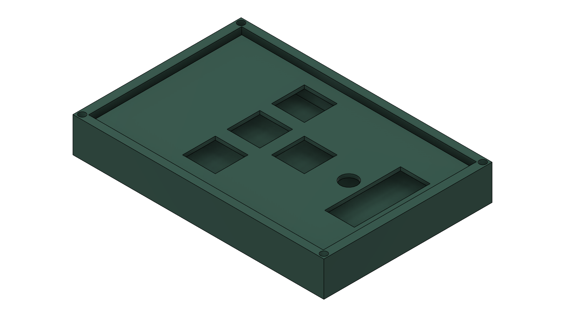
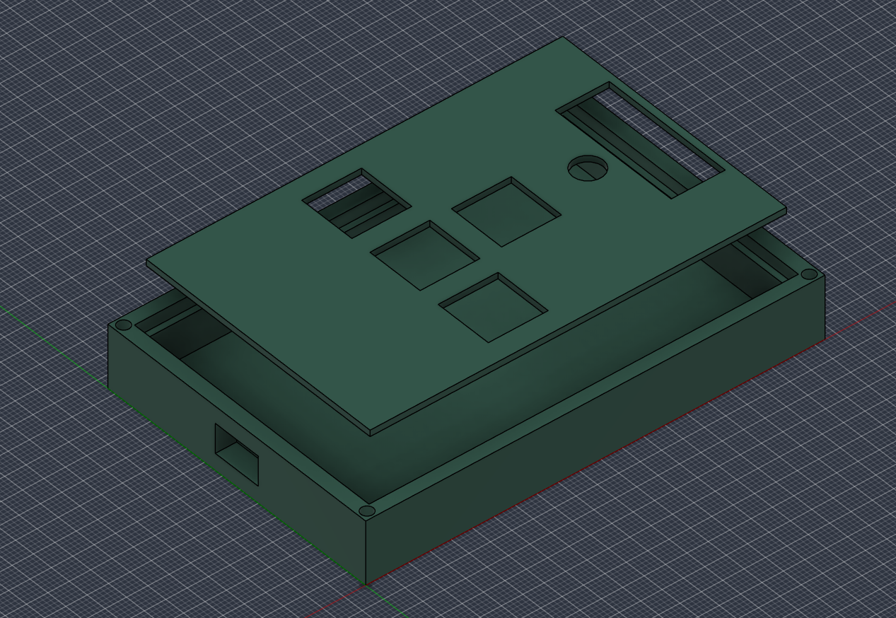
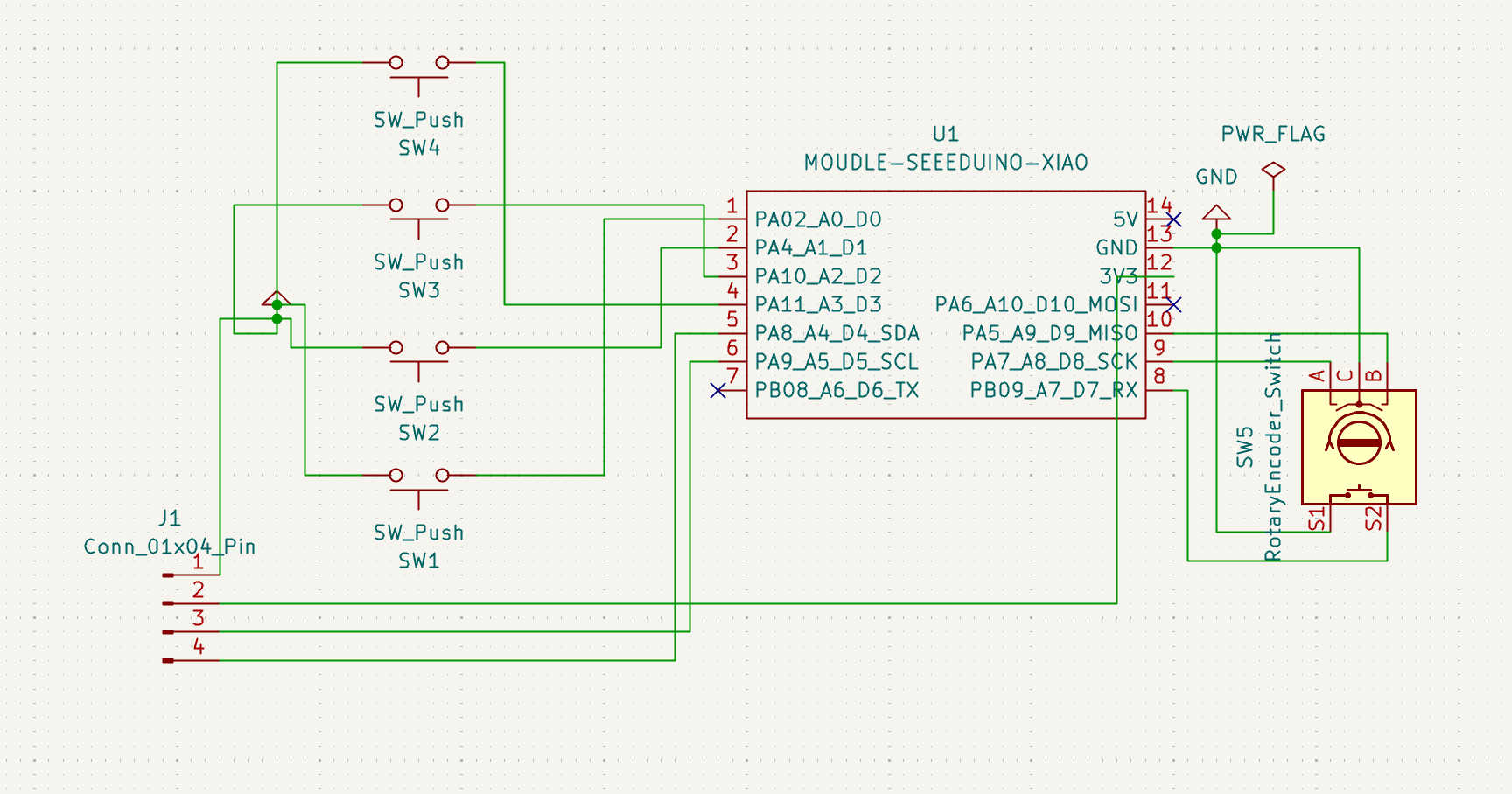
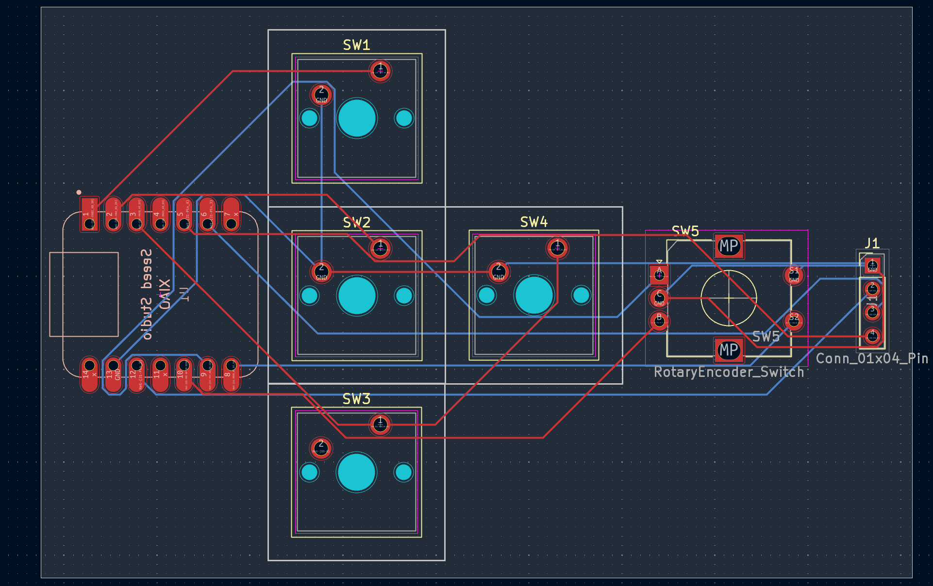
The XIAO RP2040 is soldered to the bottom layer (B.Cu) with direct access to all the board components:
| Component | Function | XIAO Pin (KiCad Net) | RP2040 GPIO | Description |
|---|---|---|---|---|
| SW1 | Key 1 | D0 (PA02_A0_D0) | GP26 | Pulled low to GND on press |
| SW2 | Key 2 | D1 (PA4_A1_D1) | GP27 | Pulled low to GND on press |
| SW3 | Key 3 | D2 (PA10_A2_D2) | GP28 | Pulled low to GND on press |
| SW4 | Key 4 | D3 (PA11_A3_D3) | GP29 | Pulled low to GND on press |
| SW5 (Enc) | Channel A | D8 (PA7_A8_D8_SCK) | GP4 | Encoder quadrature signal A |
| SW5 (Enc) | Channel B | D9 (PA5_A9_D9_MISO) | GP3 | Encoder quadrature signal B |
| SW5 (Switch) | Encoder Push | D7 (PB09_A7_D7_RX) | GP1 | Pulled low to GND on click |
| OLED (J1 Pin 4) | I2C SDA | D4 (PA8_A4_D4_SDA) | GP6 | Serial Data line |
| OLED (J1 Pin 3) | I2C SCL | D5 (PA9_A5_D5_SCL) | GP7 | Serial Clock line |
| OLED (J1 Pin 2) | Power | 3V3 | 3.3V Rail | Logic power |
| OLED (J1 Pin 1) | Ground | GND | Ground | Common system ground |
| Item | Qty | Details | Footprint / Notes |
|---|---|---|---|
| Seeed Studio XIAO RP2040 | 1 | RP2040 microcontroller development board | Hybrid SMD / THT footprint on PCB rear |
| Cherry MX Switches | 4 | Standard mechanical keyswitches | 1.00u PCB mount footprint |
| 1U Keycaps | 4 | Standard profile keycaps (OEM / Cherry / XDA) | Fits standard MX stem |
| EC11 Rotary Encoder | 1 | Incremental encoder with tactile push switch | Alps EC12E vertical footprint |
| 0.91" OLED Display | 1 | 128x32 monochrome I2C display | 4-pin interface |
| Female Pin Header | 1 | 1x4 2.54mm pitch female header | Socket for the OLED screen |
| 3D Printed Case & Plate | 1 | Printed housing (PLA or PETG) | Case STL files |
| Hardware | 4 | M2 or M3 screws | Secures the plate to the case |
PrasinoPad employs Direct-pin mapping in QMK:
DIRECT_PINS pin mappings for switches with GP26, GP27, GP28, and GP29.ENCODERS_PAD_A { GP4 } and ENCODERS_PAD_B { GP3 }. The encoder switch will be mapped as a regular key in the direct matrix (GP1).OLED_ENABLE = yes and OLED_DRIVER = SSD1306 in rules.mk and configure I2C pins to GP7 (SCL), GP6 (SDA).RPI-RP2) and copy your compiled .uf2 file into that drive.| Qty | Value | Footprint | References |
|---|---|---|---|
| 4 | SW_Push | Button_Switch_Keyboard:SW_Cherry_MX_1.00u_PCB | SW1, SW2, SW3, SW4 |
| 1 | Conn_01x04_Pin | Connector_PinHeader_2.54mm:PinHeader_1x04_P2.54mm_Vertical | J1 |
| 1 | MOUDLE-SEEEDUINO-XIAO | footprints:XIAO-Generic-Hybrid-14P-2.54-21X17.8MM | U1 |
| 1 | RotaryEncoder_Switch | Rotary_Encoder:RotaryEncoder_Alps_EC12E-Switch_Vertical_H20mm | SW5 |
It measures 93.7 × 61.5 mm and has 2 copper layers, 1.6 mm thick.
7 parts. The full list of its parts is on this page, with links to each part's symbol and footprint where PCBKit's library has them.
From the avemro/PrasinoPad repository on GitHub, at the commit this page was made from: the board is PCB/keyboard.kicad_pcb and its schematic PCB/keyboard.kicad_sch. PCBKit opens the board in the browser, with nothing to install.
Its repository states no licence, so its author keeps all rights: ask avemro before reusing the design.
byrantech/laptop
anyon_e, a highly integrated, high end, open source laptop. Attempt the impossible.


AxxAxx/AxxSolder
STM32 Based soldering station for JBC cartridges, 9-24 VDC and USB-PD power


jamro/tiny-engineer
A small desktop robot that brings an AI coding assistant to life, physically acting out when it reads files, thinks, writes code, and finishes work.

hoglet67/RGBtoHDMI
Bare-metal Raspberry Pi project that provides pixel-perfect sampling of Retro Computer RGB/YUV video and conversion to HDMI
