2 layers57.3 × 19 mm
 av17998/ArduinoBoard1
Arduino hat board for a Arduino Mega for AATL Go-Baby-Go
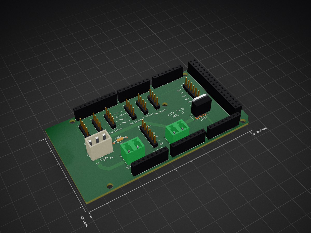
PCB V1 ATV is an open-source printed circuit board by av17998, from the av17998/ArduinoBoard repository on GitHub. It is a 2-layer board of 101.6 × 53.3 mm with 26 parts on 81 nets, routed with 100 tracks and 0 vias.
Its parts include 8 connectors, 1 resistor and 1 inductor.
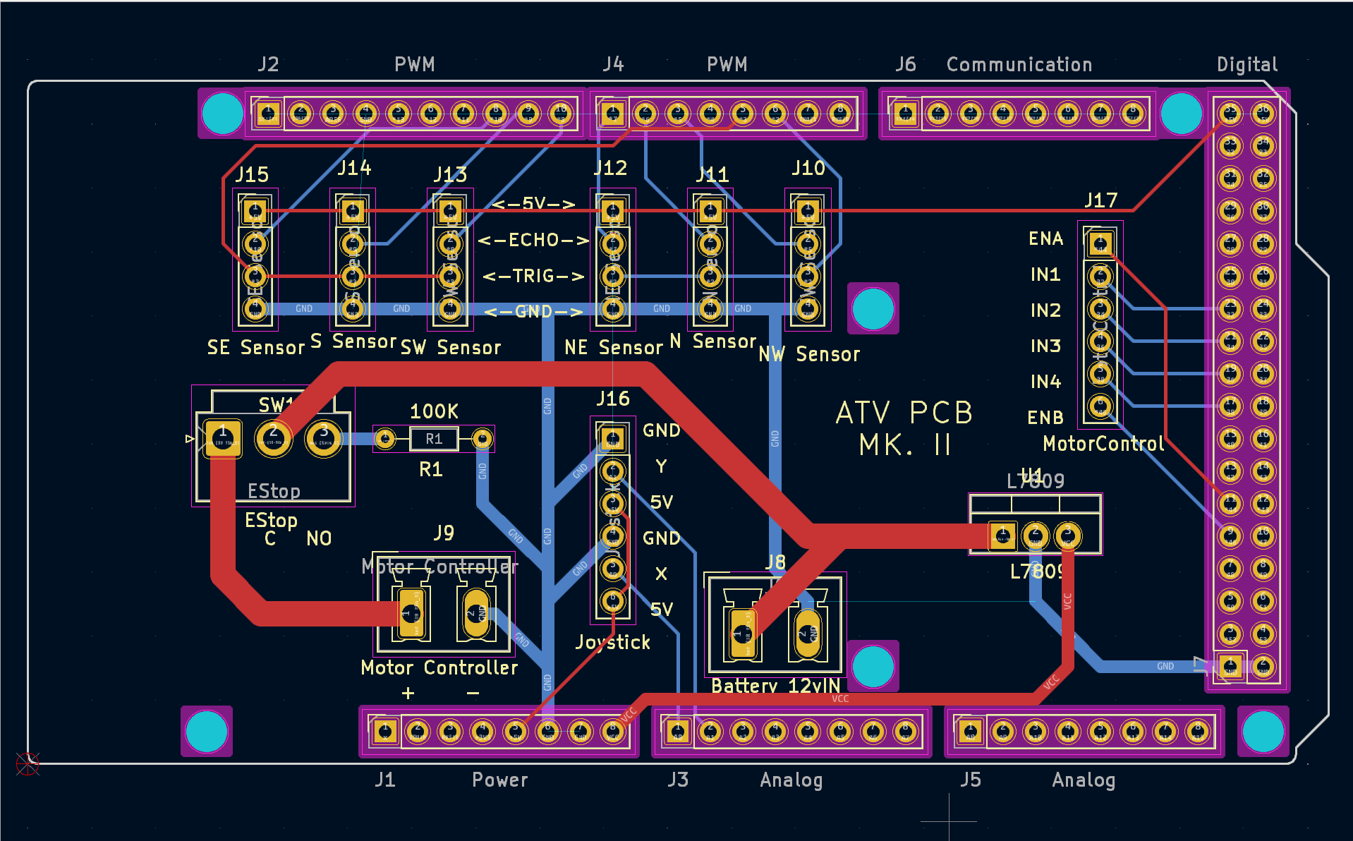
For this design, the input voltage is 12V, which is split to a linear regulator and to the motor controller for power. The 9V regulator steps down the voltage to input into the Vin pin on the Arduino mega, which will output 5V, which will power the sensors and joysticks.
There are six pin headers for HCSR04 Ultrasonic Sensors. These sensors are connected in two arrays, one forward and one backwards, designated by "North" and "South". Each array contains three sensors to get a large angle to sense objects in front of or behind the car. The current itteration of the code (uploaded in seperate repo linked below), the sensors are triggered to detect distance depending on which direction the input joystick is moving.
The joystick is a two axis joystick to be used as the only input method for the vehicle. The only info relevant to this repo is that the joystick takes two 5V and two ground inputs, with one pin each for x and y inputs.
The motor controller is getting 12V power through a single pole double through EStop switch. When in the normally open position, the motor controller will get 12V power to drive the motors. The motor controller is also connected with the other 6 pin header, which contains enable pins for each motor, and two input pins for each motor.
These files are zipped in zip folders labled by their itteration number. Each of these zip files can be uploaded to a PCB printing website or a GBR file viewer and the PCB designs should be fully portrayed.
https://github.com/av17998/Baby-Car-Code
Design property of Purdue Polytechnic Institute
There was an error made in the design that when the EStop switch was in the normally common position, the 12V will be connected straight to ground, so a change has been implemented to connect these pins through a 100k resistor.
| Qty | Value | Footprint | References |
|---|---|---|---|
| 6 | MountingHole_3.2mm | Arduino_MountingHole:MountingHole_3.2mm | MH1, MH2, MH3, MH4, MH5, MH6 |
| 2 | Analog | Connector_PinSocket_2.54mm:PinSocket_1x08_P2.54mm_Vertical | J3, J5 |
| 1 | 100K | Resistor_THT:R_Axial_DIN0204_L3.6mm_D1.6mm_P7.62mm_Horizontal | R1 |
| 1 | Battery 12vIN | Custom:Custom 2 Part Phoenix Connector | J8 |
| 1 | Communication | Connector_PinSocket_2.54mm:PinSocket_1x08_P2.54mm_Vertical | J6 |
| 1 | Digital | Connector_PinSocket_2.54mm:PinSocket_2x18_P2.54mm_Vertical | J7 |
| 1 | J10 | Connector_PinHeader_2.54mm:PinHeader_1x04_P2.54mm_Vertical | NW Sensor |
| 1 | J11 | Connector_PinHeader_2.54mm:PinHeader_1x04_P2.54mm_Vertical | N Sensor |
| 1 | J12 | Connector_PinHeader_2.54mm:PinHeader_1x04_P2.54mm_Vertical | NE Sensor |
| 1 | J13 | Connector_PinHeader_2.54mm:PinHeader_1x04_P2.54mm_Vertical | SW Sensor |
| 1 | J14 | Connector_PinHeader_2.54mm:PinHeader_1x04_P2.54mm_Vertical | S Sensor |
| 1 | J15 | Connector_PinHeader_2.54mm:PinHeader_1x04_P2.54mm_Vertical | SE Sensor |
| 1 | J16 | Connector_PinHeader_2.54mm:PinHeader_1x06_P2.54mm_Vertical | Joystick |
| 1 | J17 | Connector_PinHeader_2.54mm:PinHeader_1x06_P2.54mm_Vertical | MotorControl |
| 1 | J9 | Custom:Custom 2 Part Phoenix Connector | Motor Controller |
| 1 | PWM | Connector_PinSocket_2.54mm:PinSocket_1x10_P2.54mm_Vertical | J2 |
| 1 | PWM | Connector_PinSocket_2.54mm:PinSocket_1x08_P2.54mm_Vertical | J4 |
| 1 | Power | Connector_PinSocket_2.54mm:PinSocket_1x08_P2.54mm_Vertical | J1 |
| 1 | SW1 | Connector_JST:JST_VH_B3P-VH-B_1x03_P3.96mm_Vertical | EStop |
| 1 | U1 | Package_TO_SOT_THT:TO-220-3_Vertical | L7809 |

hackclub/OnBoard
💡 Join 1,000 teenagers and make your first PCB with a $100 grant!


harbaum/galagino
A Galaga, Pac-Man and Donkey Kong arcade emulator for the ESP32

Luos-io/luos_engine
Open-source and real-time orchestrator for cyber-physical-systems, to easily design, test and deploy embedded applications and digital twins.

google/walt
A device for measuring latency of physical sensors and outputs on phones and computers

It measures 101.6 × 53.3 mm and has 2 copper layers, 1.6 mm thick.
26 parts. The full list of its parts is on this page, with links to each part's symbol and footprint where PCBKit's library has them.
From the av17998/ArduinoBoard repository on GitHub, at the commit this page was made from: the board is PCB V1 ATV/PCB V1 ATV.kicad_pcb and its schematic PCB V1 ATV/PCB V1 ATV.kicad_sch. PCBKit opens the board in the browser, with nothing to install.
Its repository states no licence, so its author keeps all rights: ask av17998 before reusing the design.