
2 layers36.1 × 21 mm

 audiodestrukt/freedj-esp1
ESP32-A1S DJ media player: MP3/WAV playback from SD, variable speed with WSOLA keylock, OLED file browser, timecode vinyl decoder skeleton.
Index.circuit is an open-source printed circuit board by audiodestrukt, from the audiodestrukt/freedj-esp repository on GitHub, published under the GPL-3.0 licence. It is a 2-layer board of 42 × 58 mm with 36 parts on 27 nets, routed with 240 tracks and 30 vias.
It is built around the CH32V003F4P6. Its parts include 1 capacitor and 1 IC. It belongs with the RISC-V boards of this library.
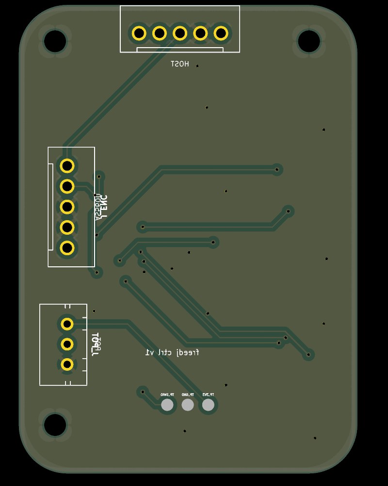
One 42 × 58 mm two-layer board under CUE / PLAY. It carries:
The AS5600 jog encoder shares the same I2C bus through the board. The host is the P4 dev board, a Pi Zero or a Teensy, over a single 5-wire cable.
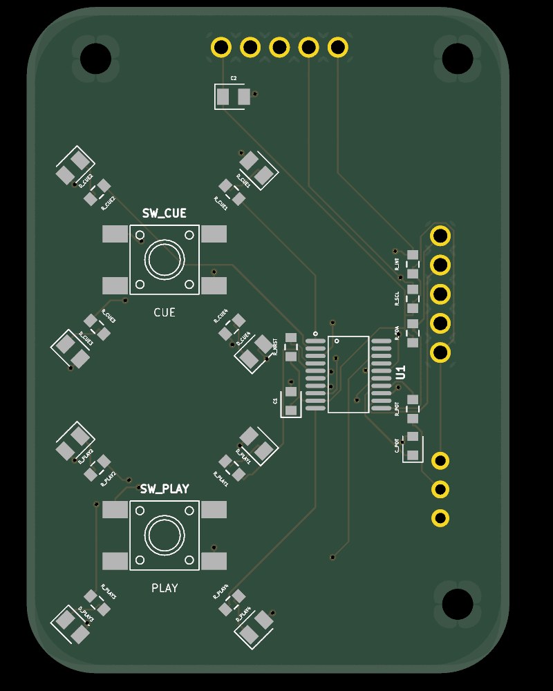
A 32-bit RISC-V microcontroller (WCH), TSSOP-20, LCSC C5187096: 26,000+ in stock at JLCPCB, about $0.29.
| CH32V003 | Use | CH32V003 | Use | |
|---|---|---|---|---|
| 1 PD4 | LED CUE 1 | 11 PC1 | SDA (I2C target) | |
| 2 PD5 | LED CUE 2 | 12 PC2 | SCL | |
| 3 PD6 | LED CUE 3 | 13 PC3 | INT to host (open drain, 10k pull-up) | |
| 4 PD7 | NRST (10k pull-up) | 14 PC4 | Fader wiper, ADC A2, 1k + 100 nF filter | |
| 5 PA1 | LED PLAY 1 | 15 PC5 | PLAY button (internal pull-up, to GND) | |
| 6 PA2 | LED PLAY 2 | 16 PC6 | CUE button | |
| 7 VSS | GND | 17 PC7 | LED CUE 4 | |
| 8 PD0 | LED PLAY 3 | 18 PD1 | SWIO (programming pad) | |
| 9 VDD | 3V3 (100 nF + 10 µF) | 19 PD2 | spare | |
| 10 PC0 | LED PLAY 4 | 20 PD3 | spare |
LEDs are driven high, with the cathode to GND:
That's about 3–5 mA each at 3.3 V. Both are JLCPCB basic parts. Use PWM in firmware to match their brightness.
The switches are ZX-QC66-7.5TP, 6 × 6 mm SMD, 7.5 mm tall (C7470157). Each is wired across its diagonal pads (1 and 4), which are switched whichever way the contacts pair up inside.
| Pin 1 | 2 | 3 | 4 | 5 | |
|---|---|---|---|---|---|
| J_HOST (back edge) | 3V3 | GND | SDA | SCL | INT |
| J_ENC (right edge, AS5600) | 3V3 | GND | DIR (tied to GND) | SCL | SDA |
| J_POT (right edge, fader) | 3V3 (one end) | wiper | GND (other end) |
The outline, the three M2.5 holes, the switch centres, the LED circle and the connector positions all come from the enclosure CAD:
gen_geom.py reads them from ../cad/machine_params.py and ../cad/ctrlboard.py.lib/geom.json.index.circuit.tsx places from that file.Keep-out: each light ring's skirt sits on r 10.8–11.8 mm around its switch centre. Only the LEDs go there, under notches in the skirt. The bosses come down onto the top face around the holes, so keep r 3 mm there clear too. build.sh doesn't check these keep-outs; the checks run were one-off.
npm ci                                   # tscircuit, same versions as freedj-3000
ln -s ~/.claude/skills/pcb-layout/scripts scripts
./build.sh
build.sh does the whole board:
fab/.The tscircuit build reports 34 pad-clearance "errors" between the MCU's own pins. These are false: they come from its rotated pill-shaped pads, and KiCad's DRC on the exported board is clean.
fab/freedj-ctrl-gerbers.zip, 2 layers, 1.6 mm.fab/freedj-ctrl-bom.csv and fab/freedj-ctrl-cpl.csv, which list 27 parts.fab/freedj-ctrl-handsolder.csv. Put the housings on the bottom side, where their outlines are on the bottom silkscreen.| Qty | Value | Footprint | References |
|---|---|---|---|
| 4 | 100Ω | tscircuit:resistor_res0603 | R_PLAY1, R_PLAY2, R_PLAY3, R_PLAY4 |
| 4 | 470Ω | tscircuit:resistor_res0603 | R_CUE1, R_CUE2, R_CUE3, R_CUE4 |
| 4 | LED | tscircuit:led_0805_color(green) | D_PLAY1, D_PLAY2, D_PLAY3, D_PLAY4 |
| 4 | LED | tscircuit:led_0805_color(yellow) | D_CUE1, D_CUE2, D_CUE3, D_CUE4 |
| 3 | tscircuit:hole_circle_holeDiameter2.7mm | , , | |
| 2 | 100nF | tscircuit:capacitor_0603 | C_POT, C1 |
| 2 | 10kΩ | tscircuit:resistor_res0603 | R_INT, R_NRST |
| 2 | 4.7kΩ | tscircuit:resistor_res0603 | R_SCL, R_SDA |
| 2 | B5B_XH_A_LF__SN_ | tscircuit:B5B_XH_A_LF_SN | J_ENC, J_HOST |
| 2 | ZX_QC66_7_5TP | tscircuit:ZX_QC66_7_5TP | SW_CUE, SW_PLAY |
| 1 | 10uF | tscircuit:capacitor_0805 | C2 |
| 1 | 1kΩ | tscircuit:resistor_res0603 | R_POT |
| 1 | B3B_XH_A_LF__SN_ | tscircuit:B3B_XH_A_LF_SN | J_POT |
| 1 | CH32V003F4P6 | tscircuit:CH32V003F4P6 | U1 |
| 1 | TP_3V3 | tscircuit:test_point_smtpad_circle_d1.5 | TP_3V3 |
| 1 | TP_GND | tscircuit:test_point_smtpad_circle_d1.5 | TP_GND |
| 1 | TP_SWIO | tscircuit:test_point_smtpad_circle_d1.5 | TP_SWIO |


gili-yankovitch/SwordOfSecrets
To solve the challenge you will need to discover a series of flags, hidden inside the sword. Each one will help you unlock the next step in the challenge, to finally reveal the ultimate secret the sword holds.


dwillmore/TSSOP20_breakout
A generic breakout board for TSSOP20 chips to a SIP header meant for breadboard use

bsidestlv/bsidestlv-2025-badge
To solve the challenge you will need to discover a series of flags, hidden inside the badge. Each one will help you unlock the next step in the challenge, to finally reveal the ultimate secret the badge holds.


bsidesorlando/2026-badge
The electronic badge for BSides Orlando 2026, themed around retro-futurism: a 1960s World's Fair vision of tomorrow, with Lil Chompy the alligator at the wheel of a flying car.
It measures 42 × 58 mm and has 2 copper layers, 1.6 mm thick.
36 parts, built around the CH32V003F4P6. The full list of its parts is on this page, with links to each part's symbol and footprint where PCBKit's library has them.
From the audiodestrukt/freedj-esp repository on GitHub, at the commit this page was made from: the board is p4/deck/hardware/ctrl-pcb/index.circuit.kicad_pcb. PCBKit opens the board in the browser, with nothing to install.
Its repository publishes it under the GPL-3.0 licence: you may reuse it on that licence's terms (keep the author's notice, and for a copyleft licence share your changes alike).