2 layers37 × 19 mm
Passive rpi hub75-adapter
hzeller/rpi-rgb-led-matrix
Controlling up to three chains of 64x64, 32x32, 16x32 or similar RGB LED displays using Raspberry Pi GPIO
2 parts4.4kGPL-2.0

 atoomnetmarc/IoT1216
Schematic, PCB files, firmware and 3d models for creating the IoT12 solder iron temperature controller for T12 compatible tips.
Display Adapter is an open-source printed circuit board by atoomnetmarc, from the atoomnetmarc/IoT12 repository on GitHub, published under the Apache-2.0 licence. It is a 2-layer board of 38.1 × 38.1 mm with 2 parts on 11 nets, routed with 61 tracks and 16 vias.
It belongs with the radio and wireless and home automation and IoT boards and the ESP32 and SAM D and SAM boards of this library.
Render
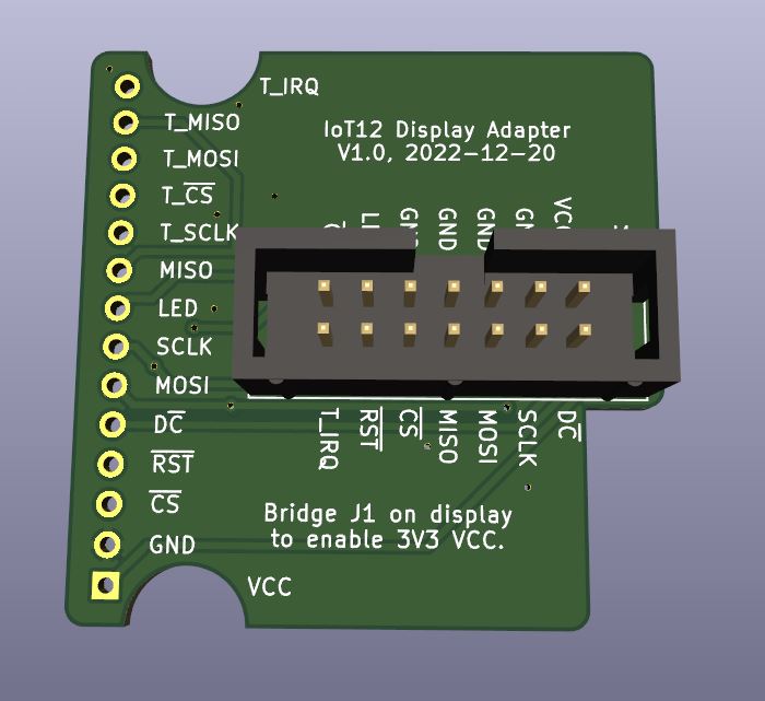
Yes, do it now. Use the BOM for identifying the components.
Results:
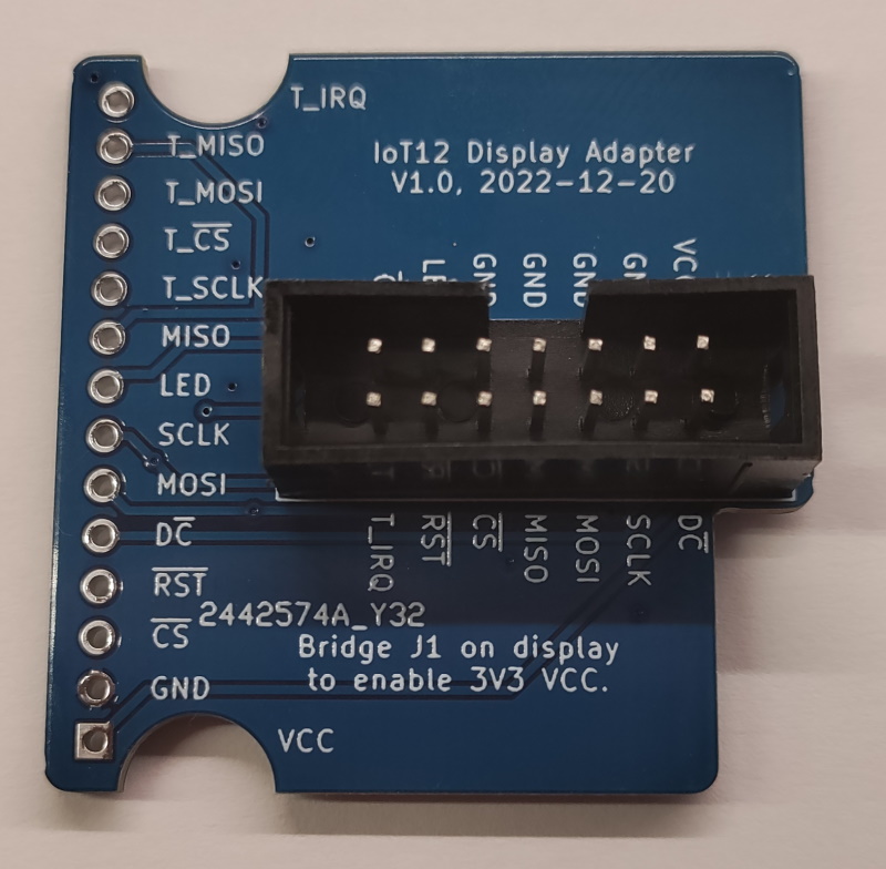
Stick a about 2.4mm high sticky pad on the bottom like this:
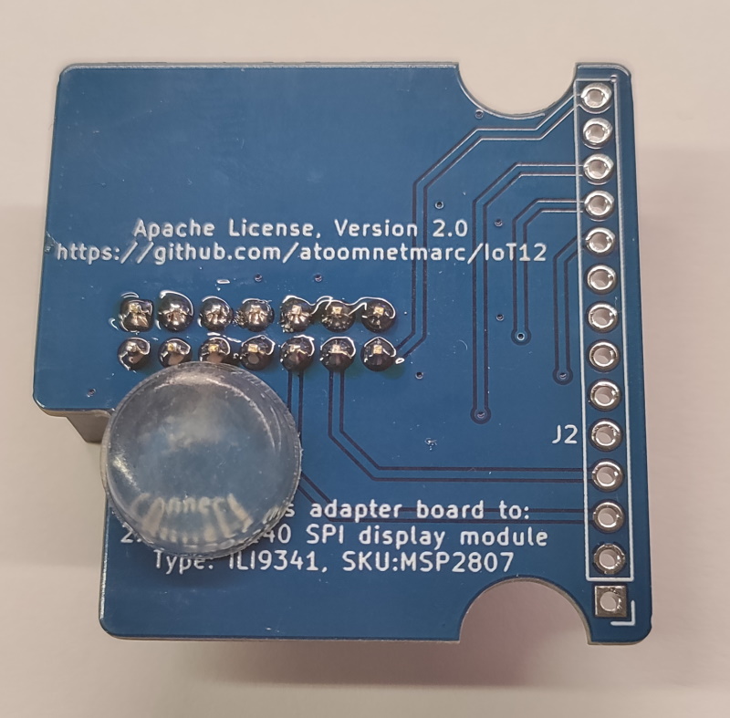
Did you bridge J1 on the TFT pcb to enable 3.3V operation? Do that before soldering the adapter board onto the TFT.
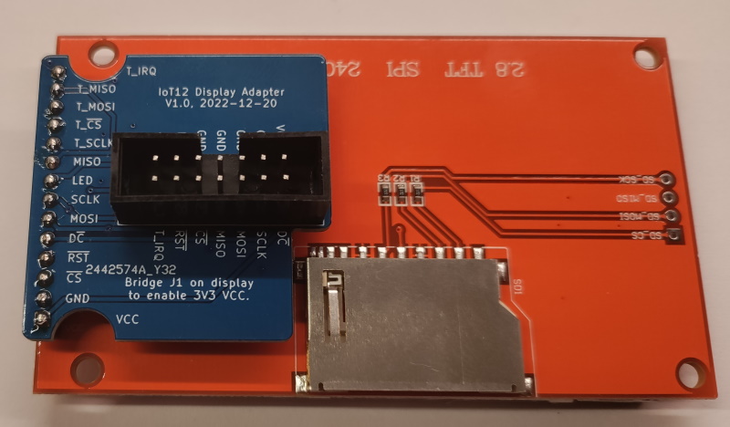
Next, solder the adapter board onto the back of the TFT display:
| Pin# | Description | Direction |
|---|---|---|
| 1 | +3.3V | Power |
| 2 | TFT_DC | Out |
| 3 | GND | Power |
| 4 | TFT_SCLK | Out |
| 5 | GND | Power |
| 6 | TFT_MOSI | Out |
| 7 | GND | Power |
| 8 | TFT_MISO | In |
| 9 | GND | Power |
| 10 | TFT_CS | Out |
| 11 | TFT_LED | Out |
| 12 | TFT_RST | Out |
| 13 | TOUCH_CS | Out |
| 14 | TOUCH_IRQ | In |
Connector to the ILI9341 2.8" touch TFT. Direction seen from the adapter board.
| Pin# | Description | Direction |
|---|---|---|
| 1 | +3.3V | Power |
| 2 | GND | Power |
| 3 | TFT_CS | Out |
| 4 | TFT_RST | Out |
| 5 | TFT_DC | Out |
| 6 | TFT_MOSI | Out |
| 7 | TFT_SCLK | Out |
| 8 | TFT_LED | Out |
| 9 | TFT_MISO | In |
| 10 | TFT_SCLK | Out |
| 11 | TOUCH_CS | Out |
| 12 | TFT_MOSI | Out |
| 13 | TFT_MISO | In |
| 14 | TOUCH_IRQ | In |

| Qty | Value | Footprint | References |
|---|---|---|---|
| 1 | IDC-Header_2x07_P2.54mm | Connector_IDC:IDC-Header_2x07_P2.54mm_Vertical | J1 |
| 1 | ILI9341 2.8" touch TFT | Connector_PinHeader_2.54mm:PinHeader_1x14_P2.54mm_Vertical | J2 |
It measures 38.1 × 38.1 mm and has 2 copper layers, 1.6 mm thick.
2 parts. The full list of its parts is on this page, with links to each part's symbol and footprint where PCBKit's library has them.
From the atoomnetmarc/IoT12 repository on GitHub, at the commit this page was made from: the board is hardware/Display Adapter/Display Adapter.kicad_pcb and its schematic hardware/Control Board/IoT12 Control Board Brain.kicad_sch. PCBKit opens the board in the browser, with nothing to install.
Its repository publishes it under the Apache-2.0 licence: you may reuse it on that licence's terms (keep the author's notice, and for a copyleft licence share your changes alike).
hzeller/rpi-rgb-led-matrix
Controlling up to three chains of 64x64, 32x32, 16x32 or similar RGB LED displays using Raspberry Pi GPIO


adamws/kicad-kbplacer
KiCad plugin for automatic keyboard's key placement and routing

Luos-io/luos_engine
Open-source and real-time orchestrator for cyber-physical-systems, to easily design, test and deploy embedded applications and digital twins.

NVNTLabs/switch2-SDEX2M2
Micro SD Express to M.2 NVME Adapter for Nintendo Switch 2

BlueSCSI/BlueSCSI-v2
BlueSCSI v2/Ultra - an open source, open hardware, SCSI emulator using the Pi Pico PR2040 and Pico 2 RP2350

ohmtech-rdi/eurorack-blocks
Software to Hardware Prototyping for Eurorack using C++, Max/Gen~ or Faust
