2 layers57.1 × 53.3 mm
Adapter shield
astuder/epc901
Experiments with ESPROS epc901 1024x1 CCD line sensor, including a spectroscope.
19 parts58

 astuder/epc90158
Experiments with ESPROS epc901 1024x1 CCD line sensor, including a spectroscope.
Epc901-breakout is an open-source printed circuit board by astuder, from the astuder/epc901 repository on GitHub. It is a 2-layer board of 61 × 36 mm with 55 parts on 37 nets, routed with 370 tracks and 41 vias.
Its parts include 23 resistors, 10 capacitors, 3 ICs, 1 connector and 1 inductor. It belongs with the sensors and measurement and interfaces and adapters boards of this library.
The ESPROS epc901 is a CCD line sensor with a resolution of 1024 monochrome pixels.
Compared to other image sensors the epc901 is very easy to drive, requiring only one voltage, I2C, a few digital I/Os and an ADC. It is also available for $33 in single units from Digi-key. On the downside, the sensor comes in a BGA package, the evaluation kit is very expensive at $1400, and we haven't seen this sensor from any other distributors than Digi-key.
This repository contains design files to build hardware and software to interact with the sensor.
For Windows users, there's now also a version of g3gg0.de SpectrumPlotter adapted to work with my epc901 firmware.
@fmilburn3 posted a write-up of this project and a few spectroscopy experiments on element14.
All hardware in this project is designed with KiCad version 5.1.6.
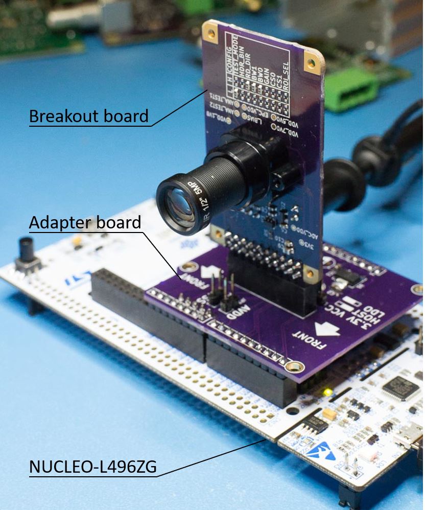
The hardware consists of a breakout board for the image sensor, and an adapter board for vertically mounting the breakout board on an ST Nulceo-144 development board.
The folder ./hardware/breakout contains the KiCad project for the epc901 breakout board.
The image sensor comes in a 2x16, 0.5 mm pitch BGA package and looks very fragile. With careful handling and placement, we successfully assembled a few boards using a stainless steel solder stencil and an unmodified toaster oven for reflow. Reflow on a hotplate probably works as well.
In addition to the image sensor and related passives, the breakout board also integrates an ADC. Footprint and firmware are compatible with Texas Instruments ADCS7476 and Analog Devices AD7476 which are 1 MSPS 12-bit ADCs with SPI-like interface.
The PCB can be ordered from OSH Park using this link.
| Pin | Function | Comment |
|---|---|---|
| 1 | GND | digital ground |
| 2 | PWR_DOWN | see epc901 datasheet |
| 3 | DATA_RDY | see epc901 datasheet |
| 4 | CLR_DATA | see epc901 datasheet |
| 5 | SHUTTER | see epc901 datasheet |
| 6 | CLR_PIX | see epc901 datasheet |
| 7 | GNDA | analog ground |
| 8 | VIDEO_P | positive video signal for use w/ external ADC, see epc901 datasheet |
| 9 | VIDEO_N | negative video signal for use w/ external ADC, see epc901 datasheet |
| 10 | GNDA | analog ground |
| 11 | GND | digital ground |
| 12 | ADC_CLK | SPI clk to on-board ADC |
| 13 | ADC_DATA | SPI data from on-board ADC |
| 14 | ADC_CS | SPI chip select for on-board ADC |
| 15 | GND | digital ground |
| 16 | 3V3 | 3.3V power supply |
| 17 | GND | digital ground |
| 18 | READ | see epc901 datasheet |
| 19 | SDA | I2C data |
| 20 | SCL | I2C clock |
| ID | Function | Comment |
|---|---|---|
| JP1 | STAR GND | Star ground point between GND and GNDA. Close to connect, leave open if GNDA and GND are connected off-board. |
| JP2 | ADC SELECTION | Selects whether to use the on-board ADC or an external ADC. External ADC will route VIDEO_P to pin 8 in the connector. |
These resistors control the configuration of the image sensor on power-up. For details, see sections 4, 7.1 and 12 in the epc901 datasheet.
The size of the board is 61 x 36 mm. The mounting holes in the corners are spaced 55 x 30 mm and have a diameter of 2.2 mm, designed for M2 screws.
The mounting holes for the lens holder are located 29 mm from the left board edge and 8 mm from top and bottom board edge. They have a diameter of 2.2 mm, designed for M2 screws.
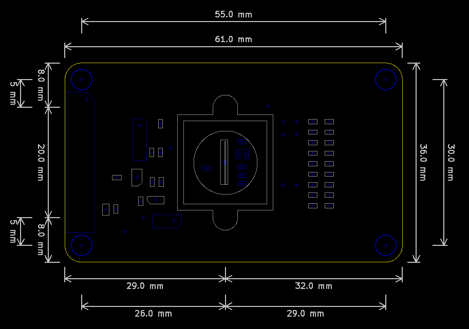
The breakout board has space and mounting holes for a lens holder. The spacing between the mounting holes is 20mm. For full coverage, the lens should support 1/2.3" or larger sensors.
For our prototypes, we chose a M12 metal lens holder w/ 20mm hole spacing and a 25mm M12 lens for 1/2" sensors. In the US, a wide selection of lens holders and lenses can be found at M12 Lenses Inc.
For use in a spectrograph, a lens may not be required. However we recommend protecting the sensor against accidental physical damage with some sort of bracket or baffel.
The folder ./hardware/adapter-shield contains the KiCad project for an adapter to mount the
epc901 breakout board on the NUCLEO evaluation board.
The layout of the adapter board follows the Arduino Shield standard. This means you could mount the adapter and sensor breakout board on any compatible MCU board. Though you will likely have to adapt the firmware to make it work.
The PCB can be ordered from OSH Park using this link.
| Arduino | Nucleo | L496ZG | Breakout | Comment |
|---|---|---|---|---|
| +3V3 | CN8 7 | +3V3 | Connected to JP1. | |
| +5V | CN8 9 | +5V | Connected to 3.3V LDO. | |
| GND | CN8 11 | GND | GND | |
| GND | CN8 13 | GND | GND | |
| D0 | CN10 16 | PD9 | PWR_DOWN | |
| D1 | CN10 14 | PD8 | DATA_RDY | |
| D2 | CN10 12 | PF15 | CLR_DATA | |
| D3 | CN10 10 | PE13 | SHUTTER | Controlled by TIM1_CH3. |
| D4 | CN10 8 | PF14 | CLR_PIX | |
| D9 | CN7 18 | PD15 | READ | |
| D10 | CN7 16 | PD14 | ADC_CS | |
| D12/MISO | CN7 12 | PA6 | ADC_DATA | |
| D13/SCK | CN7 10 | PA5 | ADC_CLK | |
| GND | CN7 8 | GND | GND | |
| A0 | CN9 1 | PA3 | VIDEO_P | |
| A1 | CN9 3 | PC0 | VIDEO_N | |
| CN10 1 | AVDD | Connected to JP3, reserved to supply analog power from Nucleo in future revisions. | ||
| CN10 3 | AVSS | Connected to JP4, alternative source for analog ground from Nucleo. | ||
| CN10 5 | GND | GND | ||
| CN10 7 | PB1 | VIDEO_P | Alternative analog pins for use with AVDD and AVSS connection in future revisions. | |
| CN10 9 | PC2 | VIDEO_N | Alternative analog pins for use with AVDD and AVSS connection in future revisions. |
| ID | Function | Comment |
|---|---|---|
| JP1 | 3.3V VCC | Select between LDO on adapter or Nucleo (HOST) as source for 3.3V power supply to breakout board. |
| JP2 | * GND | Star ground point between GND and GNDA. Close to connect, leave open if GNDA and GND are connected on breakout board. |
| JP3 | AVDD | Reserved for future use to supply power to VDD_OA of the EPC901 from the Nucleo. |
| JP4 | AVSS | Star ground point between analog ground of the breakout board and analog ground of the Nucleo. May be useful when using the ADCs of the STM32. |
The folder ./hardware/shared contains custom KiCad symbols, footprints and 3d models that can be reused across KiCad projects in this repository.
For spectroscopy experiments we created a tube to mount an optical slit and difraction grating. The 3D model is available in the folder ./hardware/spectroscope-tube.
The folder ./software/breakout contains the firmware to control the epc901 breakout board with an
STM32L4 using the NUCLEO-L496ZG evaluation board. This specific MCU and
evaluation board were chosen because we had one laying around.
The firmware is developed and built with the latest version of STM32CubeIDE (version 1.4.2 as of October 2020). To import the project into STM32CubeIDE, clone this
repository, open STM32CubeIDE and import the project with File > Open Project From File System.., and select the folder ./software/breakout. Follow the standard
procedure for building the firmware and programming the NUCLEO evaluation board.
The firmware exposes a command shell over serial. The parameters of the serial connection are 115200 8N1.
Preceding a command with @ will suppress local echo and command prompt, which is useful when developing an application that interacts with the shell.
Most commands that configure an aspect of the firmware return the current setting if no value is provided. For example exposure will return the currently configured exposure time.
| Command | Description |
|---|---|
| help | Display list of available commands. |
| help COMMAND | Display help text for command. |
| echo ON/OFF | Turn local echo on or off. |
| regread REGISTER | Read register of image sensor over I2C. |
| regwrite REGISTER VALUE | Write to value to register of image sensor over I2C. |
| reset mcu | Reset the STM32 microcontroller. |
| reset camera | Reset the camera settings, for example exposure or burst, to their defaults. |
| reset sensor | Software reset of the image sensor through I2C. |
| exposure TIME_US | Set exposure time in microseconds. |
| exposure max | Get maximum exposure time supported. |
| capture | Start capture using the configured settings. |
| capture abort | If there's a capture in progress, abort current capture. |
| transfer | read next image from the frame buffer. |
| transfer all | read all images available in the frame buffer. |
| transfer last | read last image from frame buffer, all other images will be discarded. |
| burst ON/OFF | turn burst mode on or off. |
| burst fast | Turn on burst mode with fast capture, where image capture and data read out overlap. This can result in noisier data than regular burst mode. |
| burst frames COUNT | Set number of frames to capture in a burst. |
| burst interval TIME_MS | Set interval in milliseconds at which frames are captured. 0 will capture frames at the maximum speed possible. |
| trigger ON/OFF | Enable or disable trigger. |
| trigger source EXTERNAL/LEVEL/ZONE | Select source of trigger signal. |
| trigger direction RISING/FALLING | Set which direction of a signal will trigger. for level and zone rising means above/inside level/zone, falling means NOT above/inside. |
| trigger level LEVEL | Set trigger level for level trigger source. |
| trigger zone X1 Y1 X2 Y2 | Set trigger zone defined by two corners for zone trigger source. |
The capture command will start the image capture process based on the configuration of the camera.
First the firmware checks if there's enough space in the frame buffer for the configured number of frames (1 or burst frames). An error will be returned if there is not enoug space.
Next, if trigger is enabled, the camera waits until the configured trigger condition is met.
Next, image capture starts. If burst is enabled, it will capture the configured number of frames. All frames captured are stored in a frame buffer.
After the capture process is complete, images can be read from the frame buffer with the transfer command.
The shell will respond with BUSY if the camera is waiting for a trigger or a single image capture or burst is in progress. At any time, the command capture abort will return the camera back to idle state.
External
The external trigger source is wired to pin D35/PB11 and the USER button (B1).
Trigger direction rising triggers when the signal changes from low to high, or when the button is pressed down.
Trigger direction falling triggers when the signal changes from high to low, or when the button is released.
Level
The level trigger source uses live sensor data to trigger. When starting capture, the firmware will continously capture images until the trigger condition is met or capture is aborted.
Trigger direction rising triggers when a pixel is on or above the configured trigger level.
Trigger direction falling triggers when no pixel is on or above the configured trigger level.
Zone
The zone trigger source uses live sensor data to trigger. When starting capture, the firmware will continously capture images until the trigger condition is met or capture is aborted.
Trigger direction rising triggers when a pixel is inside the configured trigger zone.
Trigger direction falling triggers when no pixel is inside the configured trigger zone.
The transfer command reads images from the frame buffer and sends them over serial. Each image is sent in two chuncks, each terminated with a linefeed.
The folder ./software/python contains a Python library that wraps the shell of the
firmware, and a few useful Python scripts that use the library.
The Python library epc901camera.py wraps the shell exposed by the firmware into an API that's easy to use from Python.
from epc901camera import Camera
camera = Camera()
camera.open("my serial port")
camera.setExposure(1000)
camera.capture()
pixels = camera.getPixels()
camera.close()
You can use sendCommand() to directly interact with the shell, which can be useful for operations that are not supported by the library yet. The following snippet writes to I2C registers of the sensor to increase the gain.
camera.sendCommand("regwrite 2 0x99")  # turn on config via regs
camera.sendCommand("regwrite 0 0x19")  # 4x gain, read-out direction same as set by resistor
See example scripts for more details.
There are three scripts to interact with the breakout board:
live.py displays output of the image sensor in realtimesnap.py captures one imageburst.py captures a series of images in a burstThe scripts are controlled with shared and a few unique command line arguments.
| Argument | live.py | snap.py | burst.py | Description |
|---|---|---|---|---|
| -h, --help | :heavy_check_mark: | :heavy_check_mark: | :heavy_check_mark: | Display help text. |
| -p PORT | :heavy_check_mark: | :heavy_check_mark: | :heavy_check_mark: | Serial port which connects to the camera board, this is the only required argument. |
| -e EXPOSURE | :heavy_check_mark: | :heavy_check_mark: | :heavy_check_mark: | Set exposure time in microseconds. If not specified, the default exposure time is 1ms (1000us). |
| -t {external,level,zone} | :heavy_check_mark: | :heavy_check_mark: | Enable trigger and select trigger source. See Trigger logic. | |
| -tdir {falling,rising} | :heavy_check_mark: | :heavy_check_mark: | Set direction of trigger logic. | |
| -tl TRIG_LEVEL | :heavy_check_mark: | :heavy_check_mark: | Set brightness for level trigger. Valid values are 0-4095. | |
| -tz x1,y1,x2,y2 | :heavy_check_mark: | :heavy_check_mark: | Define rectangle for zone trigger. Valid x values are 0-1023, valid y values are 0-4095. | |
| -td TRIG_DELAY | :heavy_check_mark: | :heavy_check_mark: | Set delay in milliseconds after trigger event before image capture starts. | |
| -f FRAMES | :heavy_check_mark: | Number of frames to capture in a burst. | ||
| -i INTERVAL | :heavy_check_mark: | Set time interval in milliseconds between frames. 0 means best effort, i.e. at maximum speed possible. As it takes 1.3ms to read out a frame, effective capture rates may be lower than the configured interval. | ||
| -fast | :heavy_check_mark: | Enable special burst mode where frames are read out of the sensor while the next exposure is captured. This may increase noise, but will increase effective burst speeds. | ||
| -gq | :heavy_check_mark: | :heavy_check_mark: | Don't display graph window. | |
| -g GRAPH_TYPE | :heavy_check_mark: | Display animated 2D graph or 3D surface plot. If argument is missing, no graph will be displayed. | ||
| -gc COLOR | :heavy_check_mark: | Select alternative color map for 3D graph. | ||
| -gpng GRAPH_FILE | :heavy_check_mark: | :heavy_check_mark: | Save graph as PNG file. | |
| -png PNG_FILE | :heavy_check_mark: | :heavy_check_mark: | Save sensor data as a gray-scale bitmap in a PNG file. | |
| -csv CSV_FILE | :heavy_check_mark: | :heavy_check_mark: | Save sensor data as CSV file. | |
| -a | :heavy_check_mark: | :heavy_check_mark: | :heavy_check_mark: | Automatically scale vertical axis of graphs based on image data. If not specified, the Y axis will go from 0 to 3000. |
| -sx px1,w1,px2,w2 | :heavy_check_mark: | :heavy_check_mark: | :heavy_check_mark: | Scale labels of horizontal axis of 2D graphs by linear interpolation based on two points, for example to reflect wavelengths in a spectrograph. If not specified, the X axis will be labelled with pixel positions 0-1024. |
Unless stated otherwise, all software in this project is licensed under the terms of MIT License.
The main exception are files imported from the STM32 SDK (./software/breakout/Drivers), and a few files
auto-generated by STM32CubeIDE. See source code for applicable license terms.
All hardware in this project is licensed under the terms of CERN Open Hardware Licence Version 2 - Permissive.
See LICENSE-SW and LICENSE-HW for additional details.
| Qty | Value | Footprint | References |
|---|---|---|---|
| 15 | DNP | Resistor_SMD:R_0603_1608Metric | R2, R10, R11, R12, R13, R14, R15, R16, R17, R19, R21, R23, R24, R25, R26 |
| 10 | TestPoint | TestPoint:TestPoint_Pad_D1.0mm | TP1, TP2, TP3, TP4, TP5, TP6, TP7, TP8, TP9, TP10 |
| 5 | 1uF | Capacitor_SMD:C_0603_1608Metric | C1, C2, C5, C6, C7 |
| 4 | 10K | Resistor_SMD:R_0603_1608Metric | R18, R20, R22, R27 |
| 4 | MountingHole_Pad | MountingHole:MountingHole_2.2mm_M2_DIN965_Pad | H1, H2, H3, H4 |
| 2 | 0.1uF | Capacitor_SMD:C_0603_1608Metric | C8, C10 |
| 2 | 0R | Resistor_SMD:R_0603_1608Metric | R3, R4 |
| 2 | 2.2uF | Capacitor_SMD:C_0603_1608Metric | C3, C4 |
| 1 | 100R | Resistor_SMD:R_0603_1608Metric | R5 |
| 1 | 10uF | Capacitor_SMD:C_0805_2012Metric | C9 |
| 1 | 56K 1% 100ppm/K | Resistor_SMD:R_0603_1608Metric | R1 |
| 1 | 600R @100M | Inductor_SMD:L_0603_1608Metric | L1 |
| 1 | AD747x | Package_TO_SOT_SMD:SOT-23-6 | U3 |
| 1 | Conn_02x10_Odd_Even | Connector_PinHeader_2.54mm:PinHeader_2x10_P2.54mm_Vertical | J1 |
| 1 | EPC901 | epc901:epc901 | U1 |
| 1 | Jumper_3_Bridged12 | Connector_PinHeader_2.54mm:PinHeader_1x03_P2.54mm_Vertical | JP2 |
| 1 | Jumper_NC_Small | Connector_PinHeader_2.54mm:PinHeader_1x02_P2.54mm_Vertical | JP1 |
| 1 | LensMount | epc901:lensholder-m12-20mm | H0 |
| 1 | REF3030 | Package_TO_SOT_SMD:SOT-23 | U2 |
astuder/epc901
Experiments with ESPROS epc901 1024x1 CCD line sensor, including a spectroscope.

davidphilipbarr/Sweep
Sweep - a small promicro based keyboard inspired by the Ferris.

VoronDesign/Voron-Hardware
Cool Hardware designed by the Voron Design group

hackclub/OnBoard
💡 Join 1,000 teenagers and make your first PCB with a $100 grant!

lever-tech/flake
An open-source, wireless, split ergonomic keyboard designed to be productive, healthy, and enjoyable. [formerly Anywhy Flake]

jes/scamp-cpu
A homebrew 16-bit CPU with a homebrew Unix-like-ish operating system.

CRImier/MyKiCad
My KiCad boards. Can't be bothered uploading individually anymore, so here you go.

rgoulter/keyboard-labs
Repo with my PCB designs and keyboard firmware

dcpedit/dissatisfaction30
To get the PCB manufactured, upload dissat-pcb.zip to JLCPCB, select your desired PCB color while keeping all the other default options, and place your order (minimum 5).
It measures 61 × 36 mm and has 2 copper layers, 1.6 mm thick.
55 parts. The full list of its parts is on this page, with links to each part's symbol and footprint where PCBKit's library has them.
From the astuder/epc901 repository on GitHub, at the commit this page was made from: the board is hardware/breakout/epc901-breakout.kicad_pcb. PCBKit opens the board in the browser, with nothing to install.
Its repository states no licence, so its author keeps all rights: ask astuder before reusing the design.