

2 layers100 × 50 mm
 Asterisk-Projects/CatearTronics2
Soldering the components onto the pcb is pretty simple by design. I used exclusively THT components as to make it as accessible as possible to anyone who wanted to construct a working set of ears.
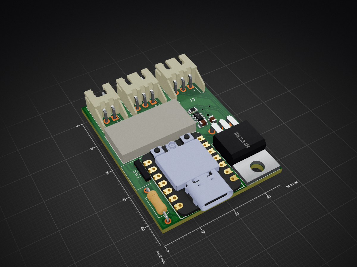
Servo reciever board is an open-source printed circuit board by Asterisk-Projects, from the Asterisk-Projects/CatearTronics repository on GitHub, published under the GPL-3.0 licence. It is a 2-layer board of 34.9 × 46.2 mm with 12 parts on 20 nets, routed with 88 tracks and 3 vias.
It is built around the TP4057 and IRLZ34N. Its parts include 3 ICs, 3 connectors, 2 capacitors, 2 resistors and 1 transistor. It belongs with the robots and motor control boards of this library.
Soldering the components onto the pcb is pretty simple by design. I used exclusively THT components as to make it as accessible as possible to anyone who wanted to construct a working set of ears.
That being said, if this is your first time with soldering, or you want to sanity check your progress, feel free to look below;
Strangest/trickiest part first, soldering the esp32 onto the board, when some of the pads aren't designed to be THT
Stealing the idea from some pi portable projects, the pcb has a place to line up and then solder pads directly, as if they were THT components, minus needing the pins
https://github.com/user-attachments/assets/6ff89706-0427-4854-b957-33d2748519fc
If you can see clearly through the pin holes on the pcb, that should be a good rule of thumb for having the solder make a proper connection
https://github.com/user-attachments/assets/05a7b818-2d18-4018-bafd-15a15622c9a0
https://github.com/user-attachments/assets/03d54e9b-8dcf-416b-b4e0-458c89ab1afb
https://github.com/user-attachments/assets/d8faf033-5a61-4b14-b7ea-404d335dd54e
3.5) Bonus step, at this point if you want to use a multimeter to make sure the ground pin on the ESP32-C6 is matching the pcb pad, now's a good time to do so
Topdown Solder view:
https://github.com/user-attachments/assets/c2cd6672-b03a-478b-8b81-bdf5427299b8
Close up on Solder view:
https://github.com/user-attachments/assets/e28facec-703d-47a0-a3c1-61f9552d93e6
If in doubt for the esp32 pins, you can always use a multimeter to check continuity
https://github.com/user-attachments/assets/20d25132-c803-4f49-b0af-fe24123dfbe5
There are 2 ways to solder the Boost Module to the board. Either 1, Soldering pins to the boost module, and then soldering that to the pcb. Or 2, Similar to the method above lining up the holes with the pads on the pcb and melting solder through both pcbs
I prefer 2, as it keeps everything flush with the board
Solder pins to the Module first
Solder those pins through to the pcb
https://github.com/user-attachments/assets/08f4d33c-642c-415e-a15c-a5704ee6e2ea
https://github.com/user-attachments/assets/1d07b14f-766c-47ba-81a9-1c2fe7a4f486
https://github.com/user-attachments/assets/4063684e-56e4-4524-bf9f-1d977909b193
https://github.com/user-attachments/assets/2640912d-a5d6-4e48-8f24-30c52ad5f29a
https://github.com/user-attachments/assets/9ac71b3d-dca0-4e95-a607-c60646f1eb5f
This is just a basic THT Soldering process
Poke through the hole, bend the pins against the pcb solder it in
https://github.com/user-attachments/assets/1a070582-4408-457d-8ebb-37c1ecead1be
Same as for the other Misc THT Components,
https://github.com/user-attachments/assets/df840dbd-ea59-47ca-b1ab-33e0bf02b99a
Lay the Mosfet flat against the PCB, bend the pins back, secure the mosfet body itself in place if needed (Capton tapes a good choice (not sponsered, just a fan)), Solder
https://github.com/user-attachments/assets/b6d3261b-38b1-4b1d-b681-efd01017a623
Same as the other components mentioned before
Slot them in on the components side of the board, secure in place (Capton Tape: The GOATed Choice), solder in
https://github.com/user-attachments/assets/cc4804e8-4b09-44fc-ad21-e733dcd569e4
https://github.com/user-attachments/assets/bfb085b4-0174-4165-b58a-63deaa4b51ec
Similar to the other components, but differs in which specific micro slide switch you're using
the ones I used are crap ones from Amazon, and they need to be folded over like such before soldering in
https://github.com/user-attachments/assets/3c21431f-e782-4019-95dd-feee480f735e
Depending on how flimsy the switch feels in that, you can then hot glue it down if neccessary, and then solder in place
https://github.com/user-attachments/assets/8b770aa5-c993-4b1f-8861-bc5e2a48de30
After everythings soldered and assembled, the final product should look something like the following
https://github.com/user-attachments/assets/3897d042-93ec-40b2-8cee-4692d19c5c93
Servos need a specific configuration in order to work, From left to right, 5V, GND, Signal
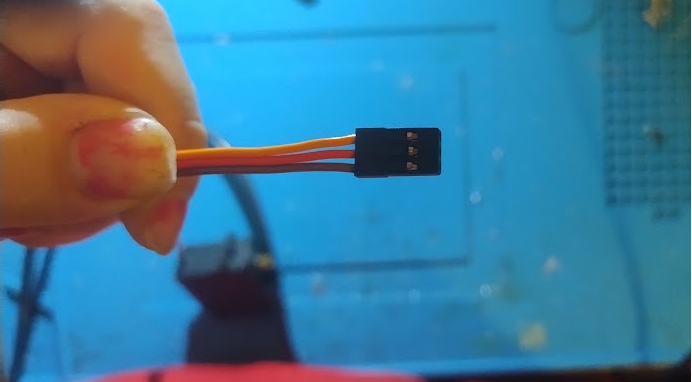
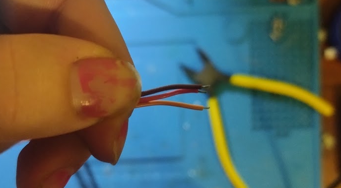
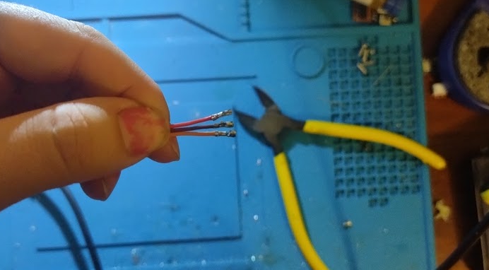
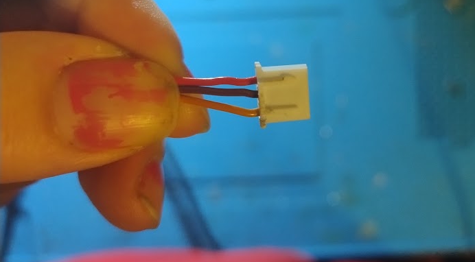
Put in right slots
???
Profit.
https://github.com/user-attachments/assets/94fb8a15-f5aa-41da-9fcb-0e23103d66a9
https://github.com/user-attachments/assets/12c65012-48b3-47f3-8964-cc56bbcdafd9
https://github.com/user-attachments/assets/45481696-18ee-453b-8a8f-0636671e7eb6
https://github.com/user-attachments/assets/a0defc09-b446-4916-8d48-d20024c9364a
https://github.com/user-attachments/assets/1194d335-ad8c-4d83-bdac-c74246ebf11d
After 3d printing everything, you'll need to attach the servos, in a way that should be fairly self explanatory.
You'll need to first install a hobby servos into the Flexible Servo holder
and then install a second servo into the Servo Attacher,
Before attaching the second servo into the first servo.
Then, you can attach the Ear print out to the Second Servo
To demonstrate this, here are some lazy diagrams
Once everythings ready for attaching to your headphones/headband, you can begin actually doing that
https://github.com/user-attachments/assets/96e62584-7f58-4617-b01d-8973c007e98b
https://github.com/user-attachments/assets/0991a19b-679e-4a93-93d0-c458842c3f06
Note: You can do this prior to attaching it to your headphones, I just didn't
https://github.com/user-attachments/assets/d4e155b1-ebcd-4a0a-8a05-d827ba0f0d81
Note: You can do this after to attaching it to your headphones, I just didn't
https://github.com/user-attachments/assets/69542e6d-8169-4057-b700-15f20d7e9b32
Finally, attach the Servo holder to the headphones using the same button strap method that was used for the pcb holder.
Repeat on the other side
Congratulations, your remote control ears are mounted and ready to use
| Qty | Value | Footprint | References |
|---|---|---|---|
| 2 | C | Capacitor_SMD:C_0805_2012Metric | C1, C2 |
| 1 | Battery Connection | Connector_JST:JST_XH_S2B-XH-A-1_1x02_P2.50mm_Horizontal | J1 |
| 1 | IRLZ34N | Package_TO_SOT_THT:TO-220-3_Horizontal_TabDown | Q1 |
| 1 | R | Resistor_SMD:R_0805_2012Metric | R2 |
| 1 | R | Resistor_THT:R_Axial_DIN0207_L6.3mm_D2.5mm_P10.16mm_Horizontal | R1 |
| 1 | SW_SPDT | custom_components:sdpt_switch_8.5mm_4mm_pole_4mm | SW1 |
| 1 | Servo X | Connector_JST:JST_XH_S3B-XH-A-1_1x03_P2.50mm_Horizontal | J2 |
| 1 | Servo Y | Connector_JST:JST_XH_S3B-XH-A-1_1x03_P2.50mm_Horizontal | J3 |
| 1 | TP4057 | Package_TO_SOT_SMD:TSOT-23-6 | U3 |
| 1 | ~ | custom_components:XIAO Esp32c6 | U2 |
| 1 | ~ | custom_components:Miniboost Module | U1 |
It measures 34.9 × 46.2 mm and has 2 copper layers, 1.6 mm thick.
12 parts, built around the TP4057 and IRLZ34N. The full list of its parts is on this page, with links to each part's symbol and footprint where PCBKit's library has them.
From the Asterisk-Projects/CatearTronics repository on GitHub, at the commit this page was made from: the board is pcb_files/servo_reciever_board.kicad_pcb and its schematic pcb_files/servo_reciever_board.kicad_sch. PCBKit opens the board in the browser, with nothing to install.
Its repository publishes it under the GPL-3.0 licence: you may reuse it on that licence's terms (keep the author's notice, and for a copyleft licence share your changes alike).

Hans-Beerman/Deurnode_ESP32-PoE
KiCad design Deurnode for the MakerSpace Leiden, based on the Olimex ESP32-PoE

3D-Printing-for-Microfluidics/3D_printer_control
2nd generation 3D printer control software

DavidJ-Saving-Time/watch-cleaner
So this is a very rough draft of code designed to run on an esp32 to control a watch cleaning machine see this YouTube video https://youtu.be/Opr75n8DbYY I'll be adding to this and making it easier for people to use.

destroyer796/3DWelder
An overbuilt 3D pen that will use a chc pro hotend and custom dc extruder powered by a power tool battery

grillbaer/solar-power-supply
Solar power harvesting for micro controller projects with li-Ion battery and highly efficient charge controller

volw/wifiOiler
Automatic, distance depending chain oiler for motorbikes with track recording (GPS).

aidtopia/spider_dropper
Mechanism to "drop" a spider (or other lightweight prop) for Halloween fun