2 layers61 × 77.8 mm

 ashmita0307/PicoLink
PicoLink is an open-source printed circuit board by ashmita0307, from the ashmita0307/PicoLink repository on GitHub. It is a 2-layer board of 34 × 60.1 mm with 55 parts on 80 nets, routed with 1,079 tracks and 140 vias.
It is built around the RP2040, W25Q32JVSSIQ and AMS1117-3.3, with the RAHPCUA20 and SP0503BAHTG among its other parts. Its parts include 15 resistors, 11 capacitors, 7 connectors, 4 switches and 3 ICs. It belongs with the RP2040 boards of this library.


An RP2040-based project for VGA graphics generation and USB composite device implementation.
PicoLink is an RP2040-based project focused on VGA graphics generation and USB communication. It uses PIO and DMA for efficient VGA output and implements a USB composite device with HID and CDC interfaces.
| Components | Description |
|---|---|
| RP2040-Mitrocontroller | Microcontroller |
| 15-Pin VGA Connector | VGA-connector |
| 33O ohm Resistors | Resistor |
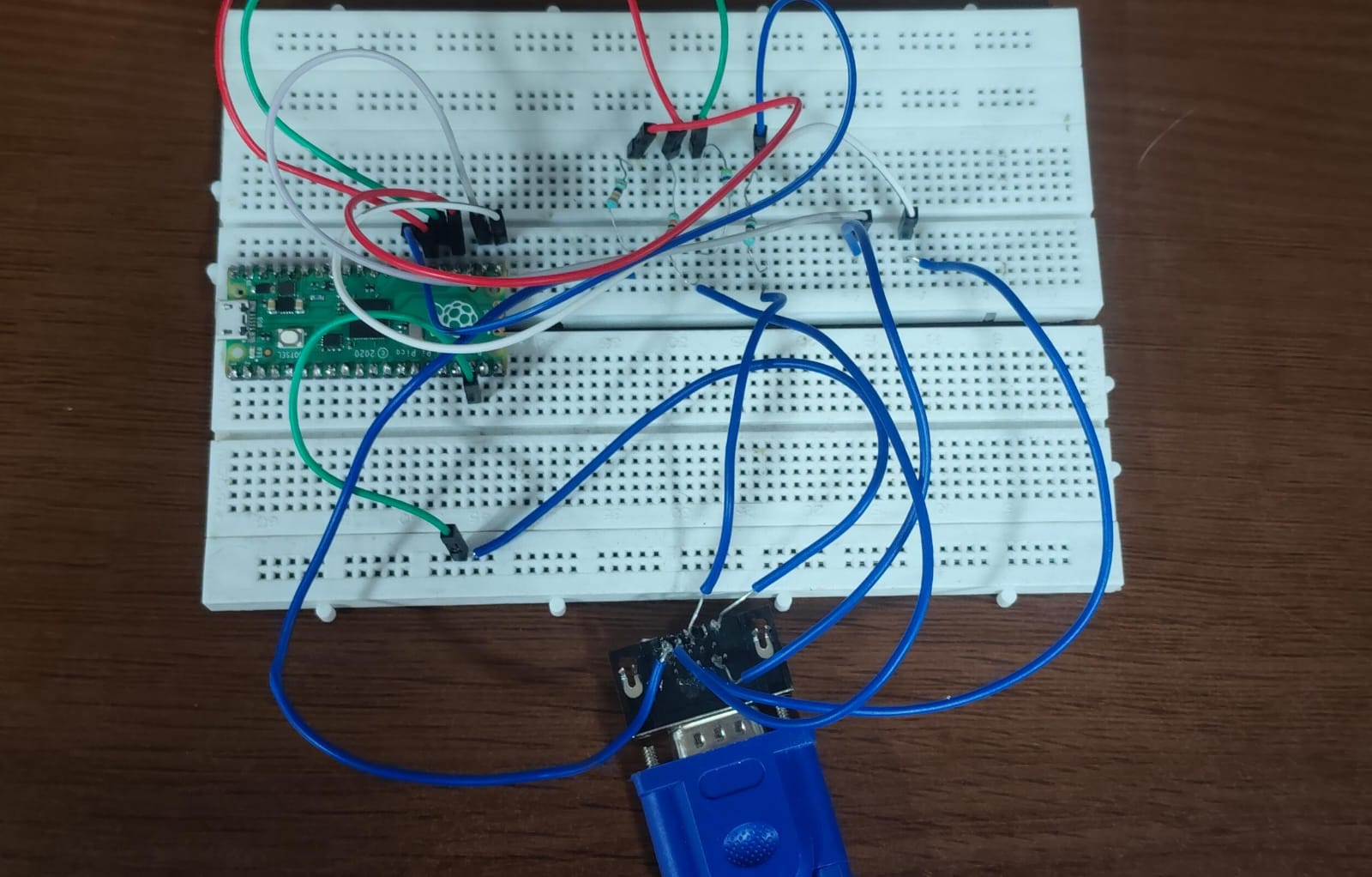

|

|

|

|
| Qty | Value | Footprint | References |
|---|---|---|---|
| 5 | 100n | Capacitor_SMD:C_0805_2012Metric | C6, C8, C9, C11, C14 |
| 5 | 1k | Resistor_SMD:R_0805_2012Metric | R5, R11, R14, R15, R16 |
| 4 | Conn_01x14_Pin | Connector_PinHeader_1.27mm:PinHeader_1x14_P1.27mm_Vertical | J6, J7, J8, J9 |
| 4 | SW_Push | Button_Switch_SMD:SW_SPST_B3U-1000P | SW2, SW3, SW4, SW5 |
| 3 | 330 | Resistor_SMD:R_0805_2012Metric | R7, R8, R10 |
| 2 | 10µ | Capacitor_SMD:C_0805_2012Metric | C1, C3 |
| 2 | 15p | Capacitor_SMD:C_0805_2012Metric | C12, C13 |
| 2 | 1µ | Capacitor_SMD:C_0805_2012Metric | C7, C10 |
| 2 | 27.4 | Resistor_SMD:R_0805_2012Metric | R12, R13 |
| 2 | 330R | Resistor_SMD:R_0805_2012Metric | R6, R17 |
| 2 | 5.1k | Resistor_SMD:R_0805_2012Metric | R2, R3 |
| 2 | LED | LED_SMD:LED_0805_2012Metric | D1, D2 |
| 1 | 470 | Resistor_SMD:R_0805_2012Metric | R9 |
| 1 | AMS1117-3.3 | Package_TO_SOT_SMD:SOT-223-3_TabPin2 | U2 |
| 1 | Crystal_GND24 | Crystal:Crystal_SMD_Abracon_ABM8AIG-4Pin_3.2x2.5mm | Y1 |
| 1 | DE15_Pins_HighDensity_MountingHoles | Connector_Dsub:DSUB-15-HD_Socket_Horizontal_P2.29x1.90mm_EdgePinOffset3.03mm_Housed_MountingHolesOffset4.94mm | J3 |
| 1 | G*** | kibuzzard-6A7FFF38 | kibuzzard-6A7FFF38 |
| 1 | G*** | kibuzzard-6A7FFBEB | kibuzzard-6A7FFBEB |
| 1 | G*** | kibuzzard-6A7FFFF4 | kibuzzard-6A7FFFF4 |
| 1 | G*** | kibuzzard-6A81CC8C | kibuzzard-6A81CC8C |
| 1 | G*** | kibuzzard-6A7FFF5E | kibuzzard-6A7FFF5E |
| 1 | G*** | kibuzzard-6A81CC73 | kibuzzard-6A81CC73 |
| 1 | G*** | kibuzzard-6A7FFF22 | kibuzzard-6A7FFF22 |
| 1 | G*** | kibuzzard-6A7FFF8E | kibuzzard-6A7FFF8E |
| 1 | G*** | kibuzzard-6A80000C | kibuzzard-6A80000C |
| 1 | G*** | kibuzzard-6A81CC96 | kibuzzard-6A81CC96 |
| 1 | LOGO | LOGO | G*** |
| 1 | RAHPCUA20 | Connector_USB:USB_A_TE_292303-7_Horizontal | J4 |
| 1 | RP2040 | Package_DFN_QFN:QFN-56-1EP_7x7mm_P0.4mm_EP3.2x3.2mm | U1 |
| 1 | SP0503BAHT | Package_TO_SOT_SMD:SOT-143 | D7 |
| 1 | USB_C_Receptacle_USB2.0_16P | Connector_USB:USB_C_Receptacle_GCT_USB4105-xx-A_16P_TopMnt_Horizontal | J1 |
| 1 | W25Q32JVSS | Package_SO:SOIC-8_5.3x5.3mm_P1.27mm | U5 |
It measures 34 × 60.1 mm and has 2 copper layers, 1.6 mm thick.
55 parts, built around the RP2040, W25Q32JVSSIQ, AMS1117-3.3 and RAHPCUA20. The full list of its parts is on this page, with links to each part's symbol and footprint where PCBKit's library has them.
From the ashmita0307/PicoLink repository on GitHub, at the commit this page was made from: the board is PCB Files/PicoLink.kicad_pcb and its schematic PCB Files/PicoLink.kicad_sch. PCBKit opens the board in the browser, with nothing to install.
Its repository states no licence, so its author keeps all rights: ask ashmita0307 before reusing the design.


gianluca-rainis/Z80DevBoard
An advanced development board for the Z80 microprocessor, powered by an RP2040.


gaelperez16/raspberry-pi-2040-PCB-design
Simple raspberry pi 2040 design w/ LIS3DH PCB design