2 layers137 × 33.8 mm

 asanza/keithley_1998
Upgrades for an old Keithley 199 multimeter
KeithleyUpgrade is an open-source printed circuit board by asanza, from the asanza/keithley_199 repository on GitHub, published under the GPL-3.0 licence. It is a 4-layer board of 85 × 60 mm with 75 parts on 109 nets, routed with 854 tracks and 86 vias.
It is built around the PIC32MX350F128L-I/PF, FT230XQ-R and TMP275AID, with the 24AA256-E/P, LM2936M-3.0 and TP1 among its other parts. Its parts include 24 resistors, 22 capacitors, 8 ICs, 7 diodes and 6 connectors. It belongs with the sensors and measurement boards and the PIC boards of this library.


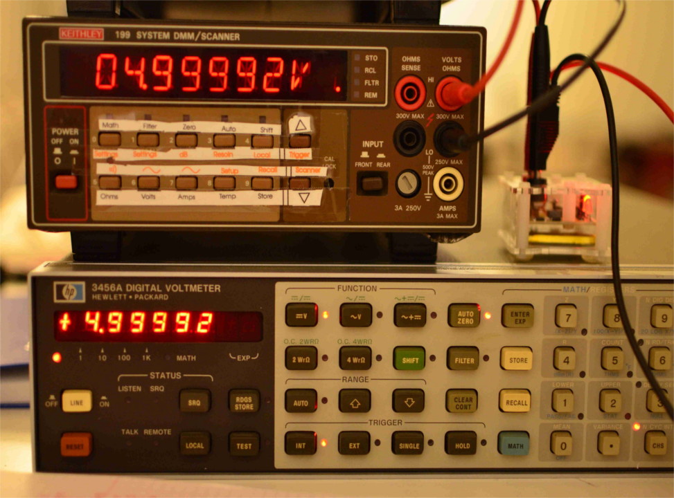
This is an upgrade replacement for the digital control board on Keithley 199 multimeters.
The Keithley 199 is a digital multimeter built in the nineties. It is capable of current, voltage and resistance measurements and also provides a gpib interface for remote control.
These multimeters contains three electronic circuit boards, one which contains the analog circuitry, including analog signal conditioning and analog digital converter, a display board which contains the user interface, and a digital control board, with a processor who controls display, gpib interface and analog digital converter.
This repository contains hardware and software files needed to build a replacement of the digital control board.
The hardware files are in Kicad format. Gerber files are (not yet) available.
The software was built with the Microchip Toolchain.
We use Ceedling for building and testing (but for comfort, MPLABX files are available).
In order to build the software, go to the root directory and do:
$rake releaseOr to perform the unit tests:
$rake test:allThe hardware is pretty basic. It contains a pic32mx controller which do the heavy lifting. An ftdi chip provides an usb interface, while two open drain drivers controll the led displays. The external trigger input and output are connected to the microcontroller through the necessary input/output protection.
TODO
The interesting part is the Control of the analog board. The analog board contains a series of switches that are controlled with a shift register. The adc conversion is performed with a discrete charge-balance adc which returns a pulse train with a pulse count proportional to the input voltage. The control of the adc is performed by the microcontroller in the digital board and should observe a precise timing in order to guarantee adc accuracy.
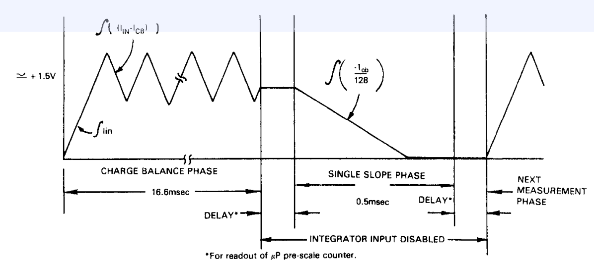
As shown in the figure above, the charge balance phase starts after the controller sends a start of conversion to the analog board. While the charge balance phase takes place, the controller counts the number of pulses it receives from the analog board. The analog board only send pulses on the up parts, thus the number of pulses is proportional to the charge acumulated. After exactly 16.66 msecs the controller sends an stop of conversion and the single slope phase starts, discharging the integrator. While discharge takes place, the controller counts the number of pulses received.
 * Copyright (c) 2015, Diego F. Asanza. All rights reserved.
 *
 * This software is free software; you can redistribute it and/or
 * modify it under the terms of the GNU Lesser General Public
 * License as published by the Free Software Foundation; either
 * version 2.1 of the License, or (at your option) any later version.
 *
 * This library is distributed in the hope that it will be useful,
 * but WITHOUT ANY WARRANTY; without even the implied warranty of
 * MERCHANTABILITY or FITNESS FOR A PARTICULAR PURPOSE.  See the GNU
 * Lesser General Public License for more details.
 *
 * You should have received a copy of the GNU Lesser General Public
 * License along with this library; if not, write to the Free Software
 * Foundation, Inc., 51 Franklin Street, Fifth Floor, Boston,
 * MA 02110-1301  USA
*| Qty | Value | Footprint | References |
|---|---|---|---|
| 9 | 100n | Capacitors_SMD:C_0805 | C3, C4, C10, C12, C14, C15, C16, C18, C20 |
| 8 | 10k | Resistors_SMD:R_0805 | R9, R10, R12, R14, R15, R16, R17, R23 |
| 4 | 220 | Resistors_SMD:R_0805 | R20, R21, R22, R24 |
| 4 | DIODE | Diodes_SMD:Diode-SMA_Standard | D1, D2, D3, D4 |
| 3 | 10n | Capacitors_SMD:C_0805 | C9, C19, C21 |
| 3 | LED | LEDs:LED-0805 | D5, D6, D7 |
| 2 | 100 | Resistors_SMD:R_0805 | R11, R13 |
| 2 | 10u | Capacitors_SMD:C_1210 | C13, C17 |
| 2 | 18p | Capacitors_SMD:C_0805 | C6, C7 |
| 2 | 1k75 | SMD_Packages:SM0805 | R5, R6 |
| 2 | 220u/10v | Capacitors_SMD:c_elec_10x10 | C11, C22 |
| 2 | 27 | SMD_Packages:SM0805 | R2, R3 |
| 2 | 47p | Capacitors_SMD:C_0805 | C1, C2 |
| 2 | 82 | personal:SOM16 | RP1, RP2 |
| 2 | MIC2981 | soic:soic-18 | U4, U5 |
| 2 | TP1 | Connect:SIL-1 | P8, P9 |
| 1 | 10K | SMD_Packages:SM0805 | R4 |
| 1 | 10u | Capacitors_SMD:C_0805 | C8 |
| 1 | 220 | SMD_Packages:SM0805 | R7 |
| 1 | 24AA256 | SOIC_Packages:SOIC-8_N | U1 |
| 1 | 4050 | SOIC_Packages:SOIC-16_Narrow | U8 |
| 1 | 4K7 | SMD_Packages:SM0805 | R1 |
| 1 | 4K7 | Resistors_SMD:R_0805 | R19 |
| 1 | 4k7 | SMD_Packages:SM0805 | R8 |
| 1 | 4u7 | Capacitors_SMD:C_1206 | C5 |
| 1 | BC850 | SMD_Packages:SOT23 | Q1 |
| 1 | CONN_8 | Pin_Headers:Pin_Header_Straight_1x08 | P18 |
| 1 | CONT | Capacitors_Elko_ThroughHole:Elko_vert_DM14_RM5 | SP1 |
| 1 | CRYSTAL_SMD_4POL | personal:XTAL_SMD_5x3_2 | X1 |
| 1 | DEBUG_PORT | personal:header_straight_2x13 | J1 |
| 1 | DISPLAY_BOARD | personal:header_straight_2x13 | J14 |
| 1 | FT230x | Housings_DFN_QFN:QFN-16-1EP_4x4mm_Pitch0.65mm | U2 |
| 1 | INDUCTOR_SMALL | SMD_Packages:SMD-1210 | L1 |
| 1 | LM2936 | SMD_Packages:DPAK2 | U6 |
| 1 | PIC32MX350F128L | QFP:TQFP-100-4 | U3 |
| 1 | R | Resistors_SMD:R_0805 | R18 |
| 1 | TC2030-MCP | Tag-Connect:TC2030-NL_SMALL | P1 |
| 1 | TMP275 | SOIC_Packages:SOIC-8_N | U7 |
| 1 | TRIGGER | Connect:bornier3 | K1 |
| 1 | USB | Connect:USB_B | JP1 |


Na55im/keithley199-upgrade
This is an upgrade replacement for the digital control board on Keithley 199 multimeters.

mandraga/SombreroBms
A battery management system (BMS) for small vehicles mainly 36V and 48V (golf carts & quads).

freeDSP/FreeDSP_Catamaran_AB
A mono contruction Differntial 1 Input 4 output ADAU1701 DSP board, 96kHz TDM8 interlink is available.


CyberPit/FreeDSP_Classic_SMD_AB_plus-II
An extended version of FreeDSP Classic SMD A/B

CyberPit/FreeDSP-FreeDSP_SMD_AB
2in4out ADAU1701 Board with selectable 2 EEPROMs, SMD resisitors, ThtoughHole Ele-Caps.


It measures 85 × 60 mm and has 4 copper layers, 1.6 mm thick.
75 parts, built around the PIC32MX350F128L-I/PF, FT230XQ-R, TMP275AID and 24AA256-E/P. The full list of its parts is on this page, with links to each part's symbol and footprint where PCBKit's library has them.
From the asanza/keithley_199 repository on GitHub, at the commit this page was made from: the board is hw.kicad/KeithleyUpgrade.kicad_pcb. PCBKit opens the board in the browser, with nothing to install.
Its repository publishes it under the GPL-3.0 licence: you may reuse it on that licence's terms (keep the author's notice, and for a copyleft licence share your changes alike).