
2 layers
Watch
KIIT-Robotic-Society/Dharma_RoboFest4.0
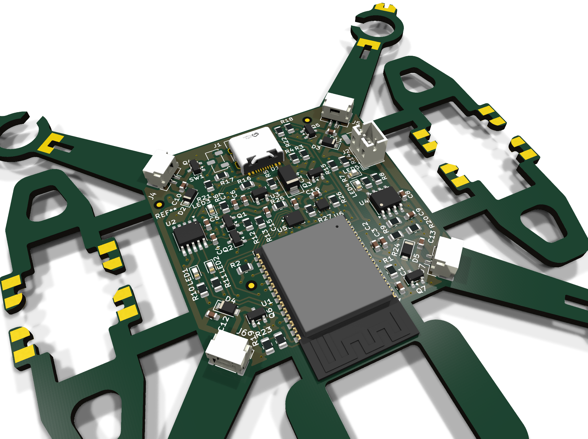
Dharma Bot is a quadruped robotic dog featuring 12-DOF locomotion, real-time sensing, and a modular subsystem design.
80 parts4MIT

 Asaf66/Drone_ESP32
Rev 2 fixes the issues found while assembling the first board:
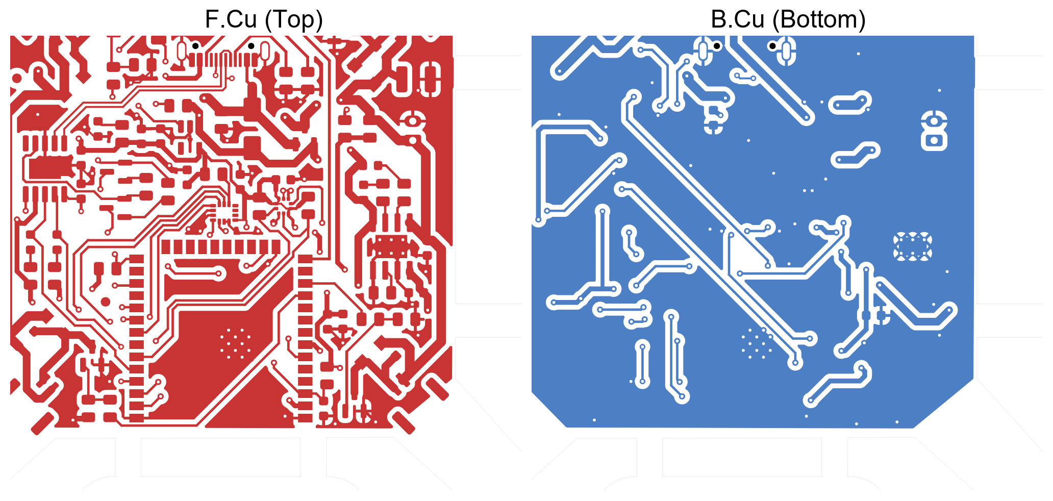
Drone ESP32 is an open-source printed circuit board by Asaf66, from the Asaf66/Drone_ESP32 repository on GitHub. It is a 2-layer board of 102.9 × 103.7 mm with 80 parts on 72 nets, routed with 660 tracks and 90 vias.
It is built around the ESP32-WROOM-32E, CH340K and LPS22HB, with the AP2112K-3.3, LSM6DS3 and TP4056-42-ESOP8 among its other parts. Its parts include 27 resistors, 19 capacitors, 10 diodes, 7 transistors and 6 ICs. It belongs with the robots and motor control boards and the ESP32 boards of this library.


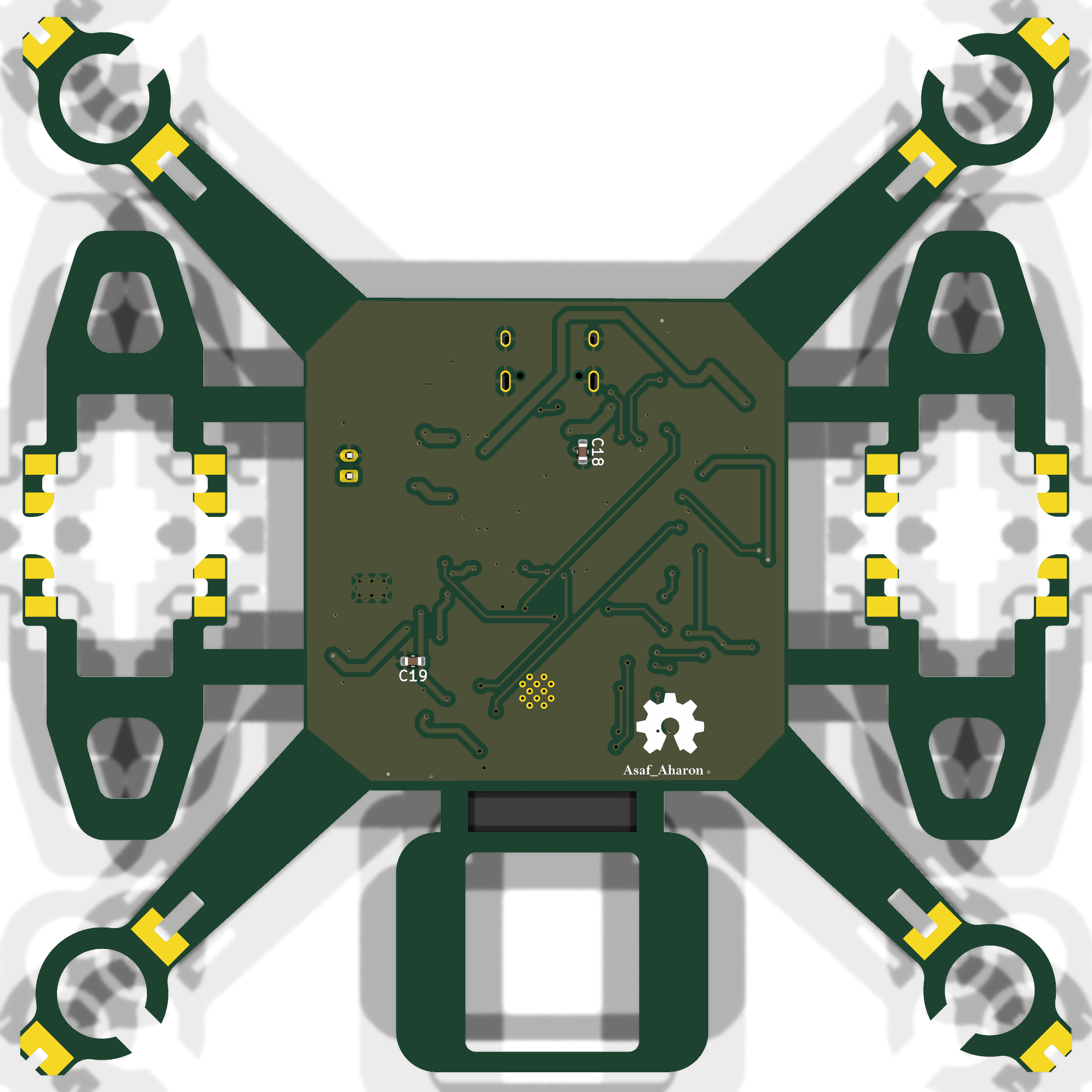
A Wi-Fi/Bluetooth micro-drone where the PCB is the airframe. Flight controller, motor drivers, sensors, and LiPo charging all sit on one 2-layer board.




flowchart LR
    USB[USB-C] --> UART[CH340K<br/>USB-UART]
    USB --> CHG[TP4056<br/>LiPo Charger]
    CHG --> BAT[(1S LiPo)]
    BAT --> LDO[AP2112K<br/>3.3V LDO]
    LDO --> MCU[ESP32-WROOM-32E]
    UART -- auto-reset --> MCU
    MCU -- SPI --> IMU[LSM6DS3<br/>6-axis IMU]
    MCU -- I2C --> BARO[LPS22HB<br/>Barometer]
    MCU -- PWM x4 --> DRV[4x SI2302<br/>MOSFET drivers]
    BAT --> DRV
DRV --> M[4x Brushed motors]| Function | Part | Notes |
|---|---|---|
| MCU | ESP32-WROOM-32E | Wi-Fi + BLE, dual-core |
| USB-UART | CH340K | BC817 auto-reset / boot circuit |
| Charger | TP4056 | 1S LiPo charging with CHG / STDBY LEDs |
| Regulator | AP2112K-3.3 | 600 mA low-dropout 3.3 V rail |
| Power path | AO3401A, SS34 | P-MOSFET USB/battery switching, Schottky protection |
| Motor drivers | SI2302 ×4 + 1N4148W ×4 | Low-side switches with flyback diodes |
| IMU | LSM6DS3 | 3-axis accelerometer + 3-axis gyroscope (SPI) |
| Barometer | LPS22HB | Absolute pressure sensor for altitude (I2C) |
| Connectors | USB-C 16P, JST-PH 2P (battery), 4× JST-GH 2P (motors) | |
| Power switch | Nidec CAS-120A | SPDT slide switch |
| Motor | Position | GPIO |
|---|---|---|
| M1 | Front right | IO13 |
| M2 | Front left | IO12 |
| M3 | Rear left | IO26 |
| M4 | Rear right | IO27 |
| PCB Layout (F.Cu / B.Cu) | 3D View (Bottom) |
|---|---|
 |  |
| Sheet | Preview |
|---|---|
| Top level | 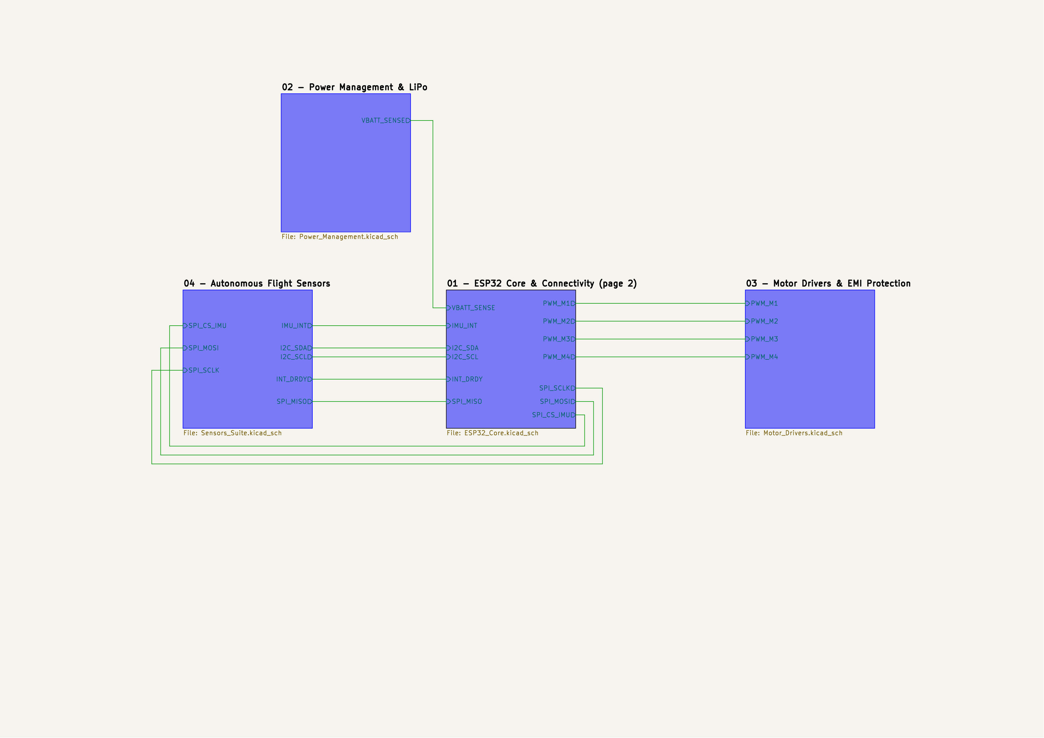 |
| 01 – ESP32 Core & Connectivity | 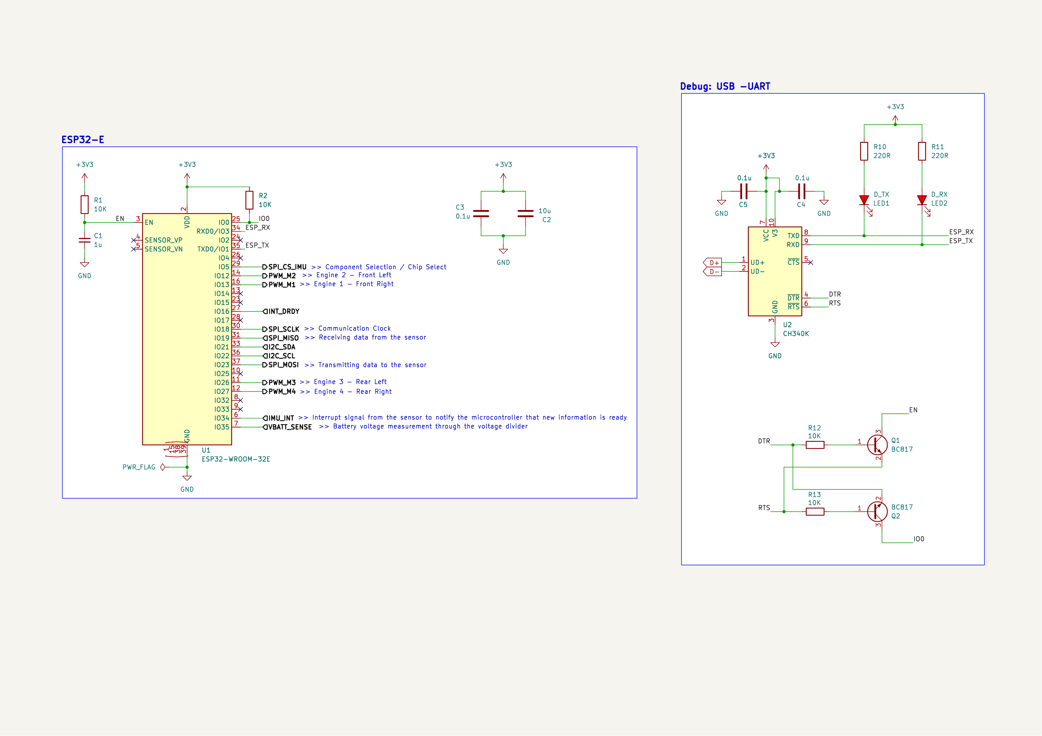 |
| 02 – Power Management & LiPo | 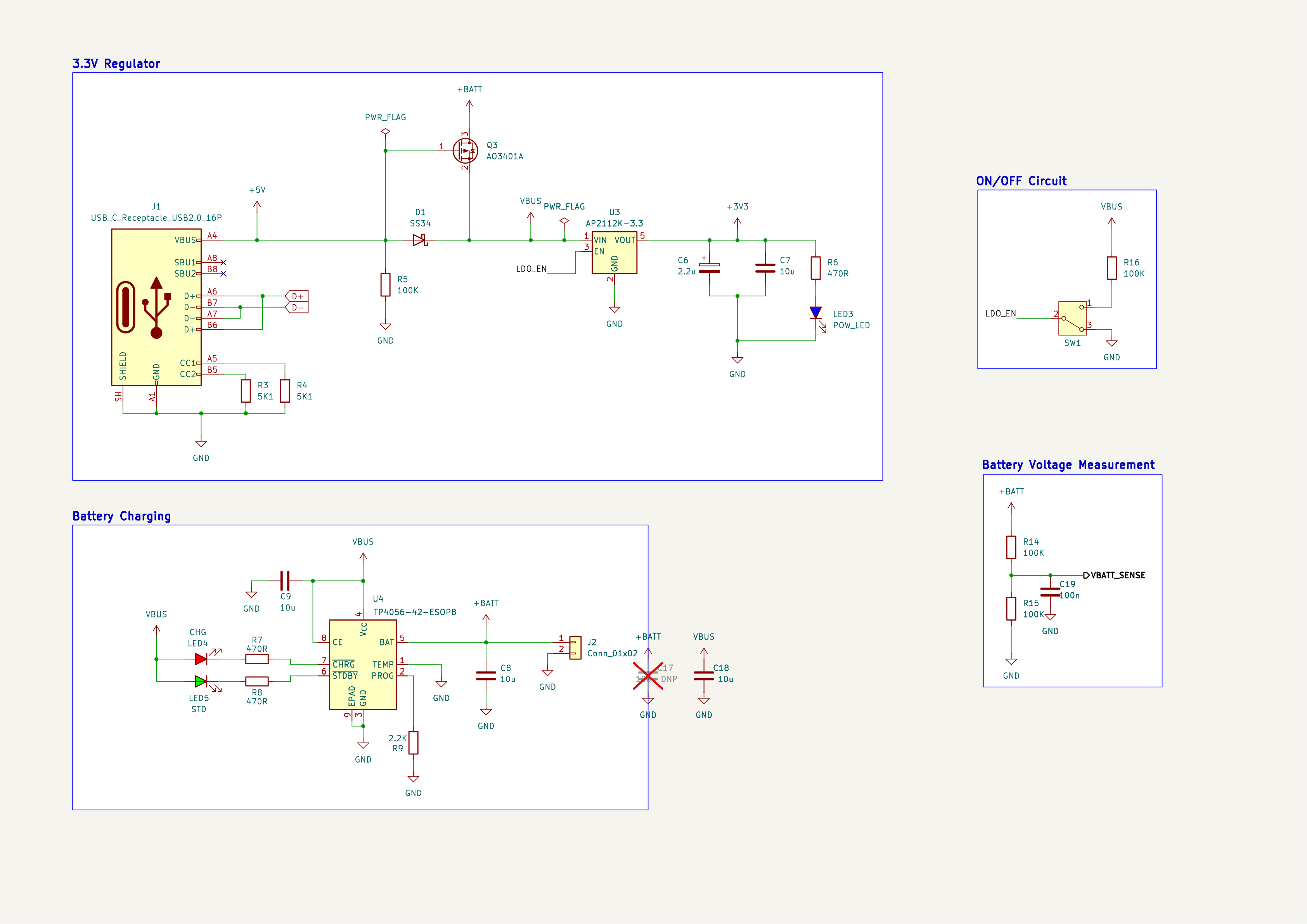 |
| 03 – Motor Drivers & EMI Protection | 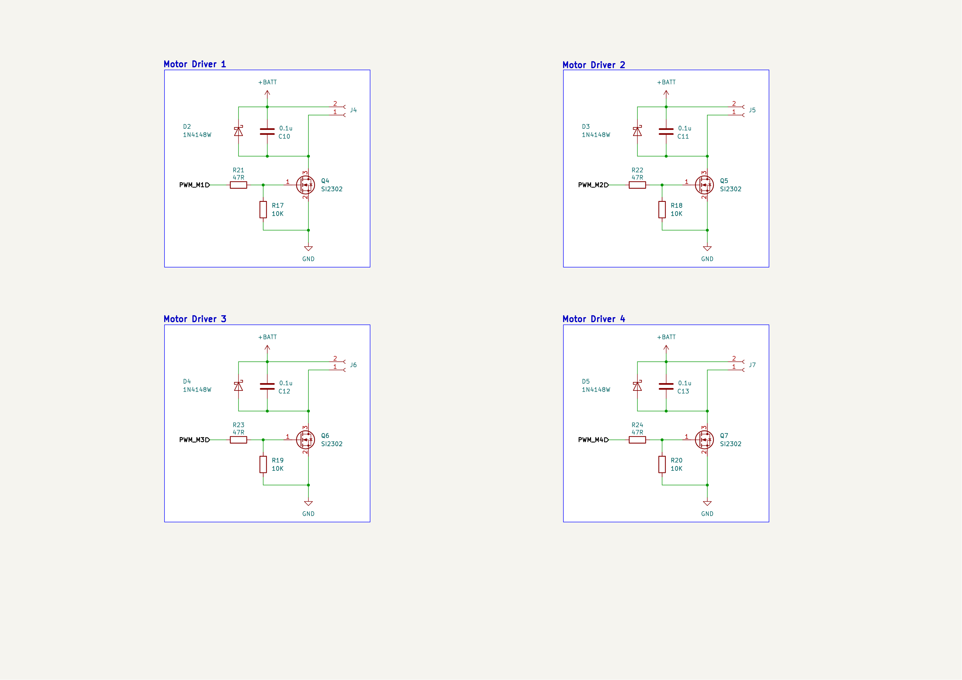 |
| 04 – Autonomous Flight Sensors | 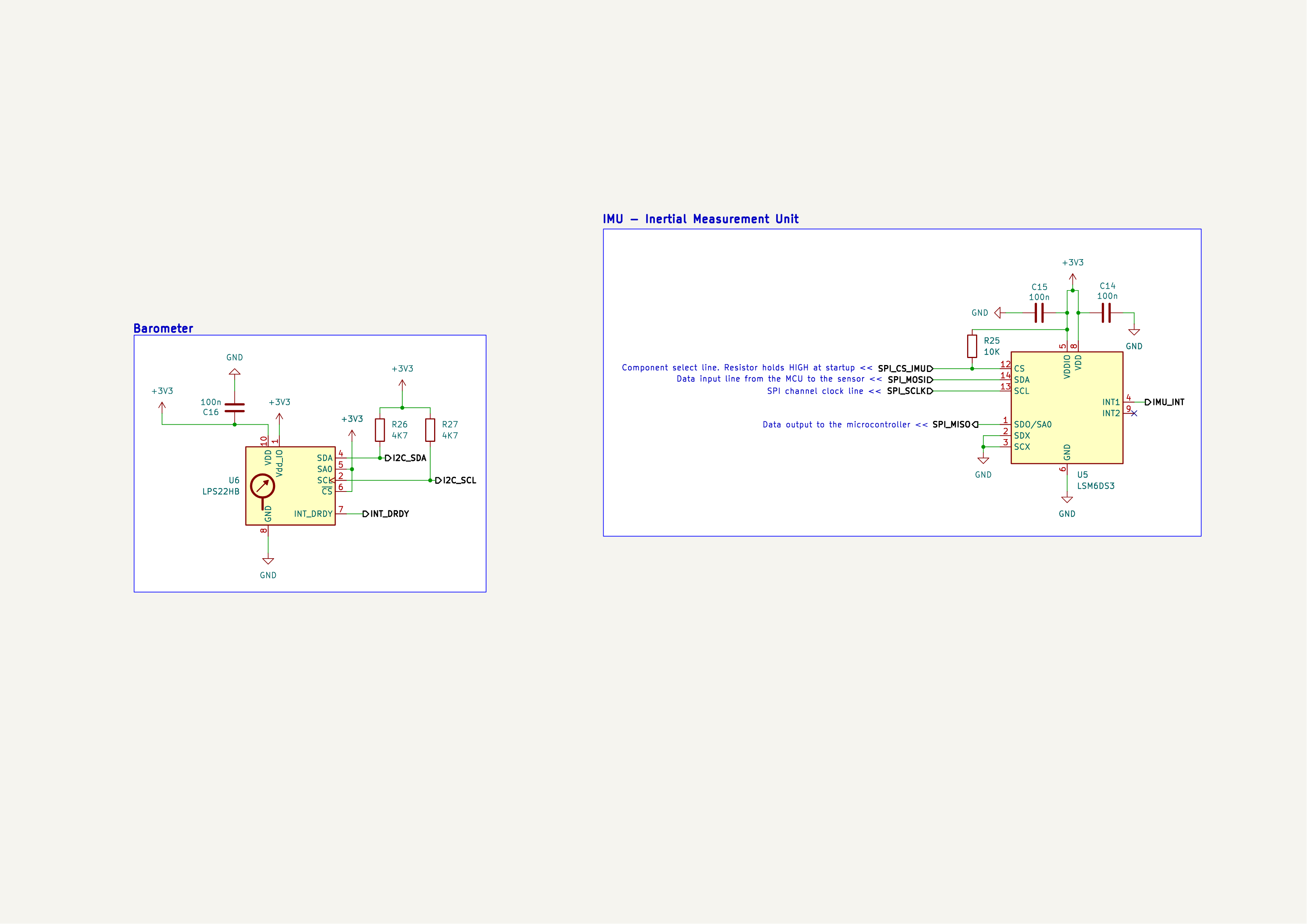 |
| Layers | Size | Thickness | Parts | Pads | Vias | Unrouted | DRC |
|---|---|---|---|---|---|---|---|
| 2 | 102.9 × 103.7 mm | 1.6 mm | 76 | 299 | 90 | 0 ✅ | 0 errors ✅ |
Rev 2 fixes the issues found while assembling the first board:
All top-side footprints are unchanged from Rev 1, so the original paste stencil can be reused. Full review: docs/Rev2_Design_Review.md.
Drone_ESP32/
├── Drone_ESP32.kicad_pro / .kicad_sch / .kicad_pcb   # KiCad project (top level + PCB)
├── Drone_ESP32.kicad_dru        # Custom DRC rules
├── ESP32_Core.kicad_sch         # Sheet 01 – MCU, USB-UART, auto-reset
├── Power_Management.kicad_sch   # Sheet 02 – USB-C, LiPo charger, LDO, power switch
├── Motor_Drivers.kicad_sch      # Sheet 03 – 4x MOSFET motor drivers
├── Sensors_Suite.kicad_sch      # Sheet 04 – IMU + barometer
├── Drone_Custom.3dshapes/       # 3D model for the USB-C connector
├── Gerbers/                     # Gerbers, drill files, JLCPCB zip
├── BOM.csv · CPL.csv            # Bill of materials and placement (JLCPCB format)
├── docs/                        # Design review
├── DATA SHEET/                  # Component datasheets
└── images/ # Renders & schematic exportsBare PCB:
Gerbers/Drone_ESP32_JLCPCB.zip to JLCPCB.Assembly (optional):
BOM.csv and CPL.csv.| Qty | Value | Footprint | References |
|---|---|---|---|
| 9 | 10K | Resistor_SMD:R_0805_2012Metric | R1, R2, R12, R13, R17, R18, R19, R20, R25 |
| 7 | 0.1u | Capacitor_SMD:C_0603_1608Metric | C3, C4, C5, C10, C11, C12, C13 |
| 5 | 10u | Capacitor_SMD:C_0603_1608Metric | C2, C7, C8, C9, C18 |
| 4 | 100K | Resistor_SMD:R_0805_2012Metric | R5, R14, R15, R16 |
| 4 | 100n | Capacitor_SMD:C_0603_1608Metric | C14, C15, C16, C19 |
| 4 | 1N4148W | Diode_SMD:Nexperia_CFP3_SOD-123W | D2, D3, D4, D5 |
| 4 | 47R | Resistor_SMD:R_0805_2012Metric | R21, R22, R23, R24 |
| 4 | Conn_01x02_Socket | Connector_JST:JST_GH_SM02B-GHS-TB_1x02-1MP_P1.25mm_Horizontal | J4, J5, J6, J7 |
| 4 | SI2302 | Package_TO_SOT_SMD:SOT-23 | Q4, Q5, Q6, Q7 |
| 3 | 470R | Resistor_SMD:R_0805_2012Metric | R6, R7, R8 |
| 2 | , | ||
| 2 | 220R | Resistor_SMD:R_0805_2012Metric | R10, R11 |
| 2 | 4K7 | Resistor_SMD:R_0805_2012Metric | R26, R27 |
| 2 | 5K1 | Resistor_SMD:R_0805_2012Metric | R3, R4 |
| 2 | BC817 | Package_TO_SOT_SMD:SOT-23 | Q1, Q2 |
| 1 | 100u DNP | Capacitor_SMD:C_1210_3225Metric | C17 |
| 1 | 1u | Capacitor_SMD:C_0603_1608Metric | C1 |
| 1 | 2.2K | Resistor_SMD:R_0805_2012Metric | R9 |
| 1 | 2.2u | Capacitor_SMD:C_0603_1608Metric | C6 |
| 1 | AO3401A | Package_TO_SOT_SMD:SOT-23 | Q3 |
| 1 | AP2112K-3.3 | Package_TO_SOT_SMD:SOT-23-5 | U3 |
| 1 | CAS-120A1 | Button_Switch_SMD:Nidec_Copal_CAS-120A | SW1 |
| 1 | CH340K | Package_SO:SSOP-10-1EP_3.9x4.9mm_P1mm_EP2.1x3.3mm | U2 |
| 1 | CHG | LED_SMD:LED_0603_1608Metric | LED4 |
| 1 | Conn_01x02 | Connector_JST:JST_PH_B2B-PH-K_1x02_P2.00mm_Vertical | J2 |
| 1 | D_RX | LED_SMD:LED_0603_1608Metric | LED2 |
| 1 | D_TX | LED_SMD:LED_0603_1608Metric | LED1 |
| 1 | ESP32-WROOM-32E | RF_Module:ESP32-WROOM-32E | U1 |
| 1 | LPS22HB | Package_LGA:ST_HLGA-10_2x2mm_P0.5mm_LayoutBorder3x2y | U6 |
| 1 | LSM6DS3 | Package_LGA:LGA-14_3x2.5mm_P0.5mm_LayoutBorder3x4y | U5 |
| 1 | POW_LED | LED_SMD:LED_0603_1608Metric | LED3 |
| 1 | SS34 | Diode_SMD:D_SMA | D1 |
| 1 | STD | LED_SMD:LED_0603_1608Metric | LED5 |
| 1 | TP4056-42-ESOP8 | Package_SO:SOIC-8-1EP_3.9x4.9mm_P1.27mm_EP2.41x3.3mm_ThermalVias | U4 |
| 1 | USB_C_Receptacle_USB2.0_16P | Connector_USB:USB_C_Receptacle_HRO_TYPE-C-31-M-12 | J1 |
The 78 most common of 80 parts.
It measures 102.9 × 103.7 mm and has 2 copper layers, 1.6 mm thick.
80 parts, built around the ESP32-WROOM-32E, CH340K, LPS22HB and AP2112K-3.3. The full list of its parts is on this page, with links to each part's symbol and footprint where PCBKit's library has them.
From the Asaf66/Drone_ESP32 repository on GitHub, at the commit this page was made from: the board is Drone_ESP32.kicad_pcb and its schematic Drone_ESP32.kicad_sch. PCBKit opens the board in the browser, with nothing to install.
Its repository states no licence, so its author keeps all rights: ask Asaf66 before reusing the design.
KIIT-Robotic-Society/Dharma_RoboFest4.0
Dharma Bot is a quadruped robotic dog featuring 12-DOF locomotion, real-time sensing, and a modular subsystem design.


mazyacin/espcam-breakout-board
high end espcam breackout board for IOT and monetering


zenglhardt/millimobile-platform
This repo contains the KiCad PCB design files for the development board verison of the MilliMobile. For more information on the platform, see the project page

schoolllex/ESPBoosted
A custom, feature-rich ESP32-WROOM-32 development board featuring built-in environmental sensors, power management, and expansion interfaces.
