Skip to the content
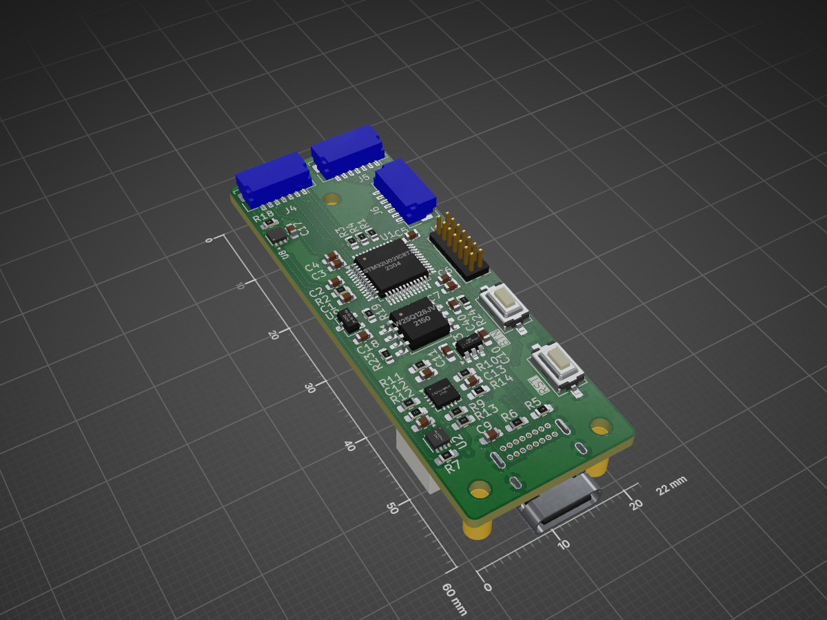
2 layers22 × 60 mmDecabox pcb, the printed circuit board in 3D

Decabox pcb

arvindsa/decabox

A compact, intelligent battery management system for 6× Decapo batteries used with cochlear speech processors. This project monitors cell voltage, ambient light, and battery state-of-charge in real-time, with visual…

Size
22 × 60 mm
Copper layers
2
Thickness
1.6 mm
Parts
61
Nets
71
Pads
262
Tracks, vias
707, 71
Pours
1
Routed
Yes
KiCad
KiCad 9.0 (file 20241229)
Created
31 May 2026
Updated
31 May 2026

Overview

Decabox pcb is an open-source printed circuit board by arvindsa, from the arvindsa/decabox repository on GitHub. It is a 2-layer board of 22 × 60 mm with 61 parts on 71 nets, routed with 707 tracks and 71 vias.

It is built around the OPT3001DNPT, W25Q128JVSIQ and AH1806-W, with the BQ24074RGTR, LP5907MFX-3.3 and AO3401A among its other parts. Its parts include 20 resistors, 19 capacitors, 8 ICs, 6 connectors and 1 transistor. It belongs with the lEDs and displays boards and the STM32 boards of this library.

Main components

6

README

README.md

DEV CI/BOX — Smart Storage & Monitoring Case for Cochlear Implant Batteries

A compact, intelligent battery management system for 6× Decapo batteries used with cochlear speech processors. This project monitors cell voltage, ambient light, and battery state-of-charge in real-time, with visual feedback via WS2812B RGB LEDs and a 128×64 OLED display.

Competition: element14 Project14 / Spring Clean 2026
Status: Complete firmware + hardware design
MCU: STM32U031C8T6 (56 MHz Cortex-M0+, 12KB SRAM)


Features

  • 6-Cell Battery Monitoring: Per-cell voltage readout via 3× ADS1115 16-bit ADCs
  • Smart LED Feedback: WS2812B RGB LEDs color-coded by battery state (green/yellow/orange/red)
  • Ambient Adaptive Brightness: OPT3001 ambient light sensor scales LED brightness 15–50%
  • Battery SOC Display: SSD1306 128×64 OLED shows voltage grid + state-of-charge %
  • USB Power Detection: BQ24074 charger with PGOOD + CHG status pins
  • Low-Power Sleep: Stop2 mode with Hall switch wake for < 15 µA idle current
  • Fuel Gauge: MAX17048 LiPo fuel gauge for accurate SOC% estimate

Hardware

PCB Design

Three boards included:

  1. Main PCB — STM32U031C8T6, BQ24074, MAX17048, OPT3001, SSD1306, AO3401 MOSFET, LP5907 LDO, W25Q128JVS SPI flash
  2. Pin PCB ×2 — ADS1115, 3× pogo connectors for Decapo cell slots, WS2812B-4020 LEDs
  3. KiCad source files — Full schematics + layouts in hardware/

MCU Pin Assignment (STM32U031C8T6, LQFP-48)

SignalGPIOFunction
I2C1_SCL/SDAPB6/PB7I²C bus — all sensors
USART2_TX/RXPA2/PA3Debug UART → ST-Link V3
WS2812B_DATAPA1 (TIM2_CH2)6× LEDs, DMA-driven @ 800 kHz
OLED_ENPA11OLED power control (AO3401 gate)
HALL_SWPA0 (EXTI0)Hall switch — Stop2 wake
PGOODPA9 (EXTI9)USB power good — Stop2 wake
FG_ALRTPA8 (EXTI8)MAX17048 low-battery alert
OPT_INTPA10 (EXTI10)OPT3001 interrupt
CHGPA12BQ24074 charge status
FLASH_CS/MOSI/MISO/SCKPA4–PA7SPI1 to W25Q128JVS (reserved)
ADS_RDY1/2/3PB10–PB12ADS1115 ready/alert pins
SWDIO/SWCLK/SWOPA13/PA14/PB3ST-Link debug

I²C Device Map

AddressDeviceFunction
0x36MAX17048Fuel gauge — LiPo SOC%
0x3CSSD1306OLED 128×64 display
0x44OPT3001Ambient light sensor
0x48ADS1115 #1Cells 1+2 voltage
0x49ADS1115 #2Cells 3+4 voltage
0x4AADS1115 #3Cells 5+6 voltage

Firmware

State Machine

text
SLEEP (Stop2)  →  HALL_SW rises or PGOOD falls  →  WAKE
WAKE           →  Read sensors → Update LEDs + OLED → SLEEP

Sleep target: < 15 µA (Stop2 mode, OLED powered off via PA11, all timers disabled).

Architecture

text
firmware/
  Core/
    Inc/
      app/
        battery_map.h      — Cell voltage (mV) → LED color mapping
        display.h          — OLED framebuffer + layout
      drivers/
        max17048.h         — Fuel gauge (I²C register map)
        ads1115.h          — ADC reads, mux config
        opt3001.h          — Lux reading, auto-range
        ssd1306.h          — OLED I²C framebuffer
        ws2812b.h          — PWM/DMA bit encoding
      main.h, stm32u0xx_hal_conf.h, stm32u0xx_it.h
    Src/
      app/
        battery_map.c      — Color thresholds
        display.c          — OLED layout rendering
      drivers/
        max17048.c, ads1115.c, opt3001.c, ssd1306.c, ws2812b.c
      main.c               — FSM, init, ISRs
      stm32u0xx_hal_msp.c  — HAL clock/GPIO setup
      stm32u0xx_it.c       — Interrupt handlers
      syscalls.c, sysmem.c, system_stm32u0xx.c
  Makefile, Drivers/, startup_stm32u031xx.s, STM32U031xx_FLASH.ld

Build & Flash

From STM32CubeIDE (GUI):

  • Open firmware/ as an existing project
  • Build via Project → Build Project
  • Flash via Run → Debug or Flash via STM32 Programmer

From CLI:

bash
cd firmware
make -C Debug/ all
# Flash via ST-Link
st-flash write Debug/decabox.bin 0x08000000
# or via STM32_Programmer_CLI
STM32_Programmer_CLI -c port=SWD -d Debug/decabox.elf -v -rst

Debug UART (115200 baud):

bash
minicom -D /dev/ttyACM0 -b 115200      # Linux/macOS
# or use PuTTY/Tera Term on COM port (Windows)

LED Color Mapping

ColorThresholdStatus
WHITE< 100 mVNo cell or sensor error
GREEN≥ 1350 mVFull
YELLOW–GREEN≥ 1200 mVGood
ORANGE≥ 1050 mVLow
RED< 1050 mVCritical

Brightness: OPT3001 lux linearly mapped to 15–50% over 1–10,000 lux range.


Hardware Details

Key Components

  • STM32U031C8T6: Ultra-low-power Cortex-M0+, 64KB flash, 12KB SRAM, 56 MHz max
  • BQ24074: Single-cell LiPo charger, VQFN-16 (requires stencil + reflow)
  • MAX17048: I²C fuel gauge for accurate battery percentage
  • OPT3001: Digital light sensor with auto-range, I²C interface
  • ADS1115: 16-bit I²C ADC (×3 for 6 differential channels)
  • SSD1306: 128×64 OLED display, I²C interface
  • WS2812B-4020: Smart RGB LEDs, 5V data line, DMA-driven
  • LP5907: 3.3V LDO, always-on supply
  • AO3401: P-channel MOSFET for OLED power switching
  • W25Q128JVS: 128 Mbit SPI NOR flash (reserved for future use)

WS2812B Protocol

800 kHz PWM/DMA on TIM2_CH2 (PA1):

  • T0H = 0.4 µs, T1H = 0.8 µs
  • Bit-expanded buffer transferred via DMA at 56 MHz
  • Reset sequence = 50 µs+ low

ADS1115 Configuration

Each ADS1115 reads 2 differential channels with configurable gain. Resistor divider on pogo contacts scales 0–6V to 0–2V ADC range. Calibration divider ratio defined in firmware/Core/Inc/drivers/ads1115.h.

Power Budget

  • Active (sensors, OLED, LEDs): ~30–50 mA
  • Stop2 idle: ~16 µA (1.5 µA MCU + 75 µA LP5907 quiescent)
  • OLED powered off: ~1 µA additional savings via PA11

Critical PCB Layout

  • BQ24074 VQFN-16 thermal pad → exposed copper + vias to bottom layer
  • I²C pull-ups: 4.7 kΩ on SDA+SCL (main board only)
  • 100 nF + 10 µF decoupling at every IC VCC
  • WS2812B: 33 Ω series resistor at MCU pin, short trace
  • W25Q128JVS: SOIC-8, 100 nF at VCC, matched SPI traces, 10 kΩ pull-up on CS

Bringing Up New Hardware

  1. 3.3V rail: Check LP5907 output with DMM
  2. Clocks: Verify main oscillator running (probe PA1 with scope after init)
  3. I²C scan: Run i2c_scan() to detect all devices (should see 0x36, 0x3C, 0x44, 0x48–0x4A)
  4. MAX17048: Read VCELL and SOC registers
  5. ADS1115: Read differential voltages from each Decapo slot
  6. OPT3001: Read lux value under ambient light
  7. OLED: Initialize framebuffer, draw test pattern
  8. WS2812B: Pulse RGB pattern, verify no glitches
  9. USB/Hall: Simulate PGOOD and HALL_SW edges, verify wake

Testing

Firmware Tests

  • RGB Color Cycle: Every 2 seconds (R→G→B), verifies WS2812B DMA
  • Battery Map: Simulated cell voltages 100–2000 mV, verify color transition thresholds
  • Sleep Mode: Enter Stop2, measure current with µA meter; wake on Hall/USB edge
  • Display Update: Read all sensors, render OLED grid every 5 seconds

PCB Bring-Up

  • Short detection: Continuity check all power/ground rails before power-on
  • Thermal camera: Monitor BQ24074 during first charge cycle
  • Oscilloscope: Probe WS2812B data line for 800 kHz pulse train
  • UART debug: Monitor init log for device discovery and sensor reads

Datasheets

All component datasheets included in datasheets/:

  • STM32U031C8T6 reference manual
  • Per-IC datasheets (BQ24074, MAX17048, OPT3001, ADS1115, SSD1306, WS2812B, etc.)

Project Structure

text
decabox/
  README.md                    ← This file
  firmware/                    — STM32CubeIDE project
    Core/                      — Application code + drivers
    Drivers/                   — STM32 HAL (auto-generated)
    Makefile, *.ld, *.s        — Build files
  hardware/
    main/                      — Main PCB (KiCad)
    pin-pcb/                   — Pin adapter board ×2 (KiCad)
  datasheets/                  — Component datasheets (PDF)

Future Extensions

  • SPI Flash (W25Q128JVS): Data logging (voltage history, charge cycles)
  • Calibration: Store ADC offset/gain in EEPROM or flash
  • OTA Firmware: Staging and validation in SPI flash
  • Wireless: Replace UART with Bluetooth LE for mobile app integration

License

Design and firmware are open source. Refer to the LICENSE file in the repository.


Contact & Attribution

Project: DEV CI/BOX — Cochlear Implant Battery Monitor
Platform: element14 Project14
MCU: STM32U031C8T6
Build: STM32CubeIDE + GCC ARM

For questions, issues, or hardware discussions, see the GitHub repository.

Parts

61
QtyValueFootprintReferences
9100nFCapacitor_SMD:C_0603_1608MetricC1, C2, C3, C4, C5, C6, C17, C18, C20
810KResistor_SMD:R_0603_1608MetricR1, R2, R3, R4, R18, R19, R23, R24
610KResistor_SMD:R_0603_1608Metric_Pad0.98x0.95mm_HandSolderR7, R8, R9, R12, R13, R14
41uCapacitor_SMD:C_0603_1608Metric_Pad1.08x0.95mm_HandSolderC8, C10, C11, C12
3Conn_01x07Connector_JST:JST_SHL_SM07B-SHLS-TF_1x07-1MP_P1.00mm_HorizontalJ4, J5, J6
3MountingHoleMountingHole:MountingHole_2.2mm_M2H1, H2, H3
210uFCapacitor_SMD:C_0603_1608MetricC19, C21
22KResistor_SMD:R_0603_1608Metric_Pad0.98x0.95mm_HandSolderR10, R11
24.7uCapacitor_SMD:C_0603_1608Metric_Pad1.08x0.95mm_HandSolderC9, C13
25.1KResistor_SMD:R_0603_1608Metric_Pad0.98x0.95mm_HandSolderR5, R6
2SW_PushButton_Switch_SMD:SW_Tactile_SPST_NO_Straight_CK_PTS636Sx25SMTRLFSSW_RST1, SW_RST2
10.1uCapacitor_SMD:C_0603_1608MetricC40
1100KResistor_SMD:R_0603_1608MetricR21
11KResistor_SMD:R_0603_1608MetricR20
11uFCapacitor_SMD:C_0603_1608MetricC7
1AH1806-WPackage_TO_SOT_SMD:SC-59U9
1AO3401APackage_TO_SOT_SMD:SOT-23Q1
1BQ24074RGTPackage_DFN_QFN:VQFN-16-1EP_3x3mm_P0.5mm_EP1.6x1.6mmU4
1Conn_ST_STDC14Connector_PinHeader_1.27mm:PinHeader_2x07_P1.27mm_VerticalJ1
1LOGOLOGOG1
1LP5907MFX-3.3Package_TO_SOT_SMD:SOT-23-5U3
1MAX17048Arvind_Power_IC:MAX17048G+T10U2
1OPT3001DNPTArvind_Sensor_IC:OPT3001U8
1SSD1306 128x32 ModuleConnector_JST:JST_SH_BM04B-SRSS-TB_1x04-1MP_P1.00mm_VerticalU10
1STM32U031C8TxPackage_QFP:LQFP-48_7x7mm_P0.5mmU1
1SolderJumper_2_OpenJumper:SolderJumper-2_P1.3mm_Open_RoundedPad1.0x1.5mmJP1
1USB_C_Receptacle_USB2.0_16PArvind_Connector_USB:USB_C_Receptacle_GCT_USB4085_NoSilkScreenoverPCBedgeJ2
1W25Q128JVSPackage_SO:SOIC-8_5.3x5.3mm_P1.27mmU11
1~Connector_JST:JST_PH_S2B-PH-SM4-TB_1x02-1MP_P2.00mm_HorizontalJ3

More from arvindsa/decabox

1
  • 2 layers70 × 11 mmDecabox pin pcb, the printed circuit board in 3D

    Decabox pin pcb

    arvindsa/decabox

    A compact, intelligent battery management system for 6× Decapo batteries used with cochlear speech processors. This project monitors cell voltage, ambient light, and battery state-of-charge in real-time, with visual…

    19 parts

Similar boards

  • 2 layers142.4 × 81.2 mmBle steno right, the printed circuit board in 3D

    Ble steno right

    crides/steno

    Embedded steno firmware + custom steno PCBs

    49 parts75MIT
  • 4 layers22.5 × 12 mmTurnipschool, the printed circuit board in 3D

    Turnipschool

    mossmann/cc11xx

    Hardware designs for CC11xx

    62 parts104GPL-2.0
  • 2 layers43 × 50 mmEsp pmsa, the printed circuit board in 3D

    Esp pmsa

    neggles/esp-pmsa

    Makefile uses Jan Mrázek's KiKit, which I cannot recommend enough, and therefore has to be available on your system.

    28 parts1CC-BY-SA-4.0
  • 2 layers20 × 13 mmSplitflap hall pcb, the printed circuit board in 3D

    Splitflap hall pcb

    SamWarmuth/SWSplitFlap

    3D printable split flap display (software/pcb/STLs), for a more detailed split flap project see https://github.com/scottbez1/splitflap

    5 parts4
  • 2 layers82 × 99 mmSolar panel side Y plus, the printed circuit board in 3D

    Solar panel side Y plus

    stanford-ssi/sapling-avionics

    2S3P Li-ion battery pack for CubeSat designs. - Fits 18650 cells (like the LG INR18650-MJ1) - Meets maximum capacity requirements of common CubeSat integrators - Uses components with radiation testing heritage -…

    24 parts
  • 2 layers100 × 100 mmSolidaq, the printed circuit board in 3D

    Solidaq

    ElvinC/solidaq

    Simple DAQ board with support for load cells, thermocouples, and a 4-20 mA pressure transmitter

    83 parts4
  • 2 layers65 × 58.5 mmCarrier, the printed circuit board in 3D

    Carrier

    open-pasture/opencollar

    OpenCollar: a virtual-fence collar you can buy assembled or build from published parts.

    100 partsApache-2.0

Questions

How big is the Decabox pcb PCB?

It measures 22 × 60 mm and has 2 copper layers, 1.6 mm thick.

What parts does the Decabox pcb use?

61 parts, built around the OPT3001DNPT, W25Q128JVSIQ, AH1806-W and BQ24074RGTR. The full list of its parts is on this page, with links to each part's symbol and footprint where PCBKit's library has them.

Where can I download the Decabox pcb KiCad files?

From the arvindsa/decabox repository on GitHub, at the commit this page was made from: the board is hardware/main/decabox-pcb.kicad_pcb and its schematic hardware/main/Hall Effect Switch.kicad_sch. PCBKit opens the board in the browser, with nothing to install.

Can I use the Decabox pcb design in my own project?

Its repository states no licence, so its author keeps all rights: ask arvindsa before reusing the design.