2 layers
Encoder
byrantech/laptop
anyon_e, a highly integrated, high end, open source laptop. Attempt the impossible.
7 parts4.3kMIT
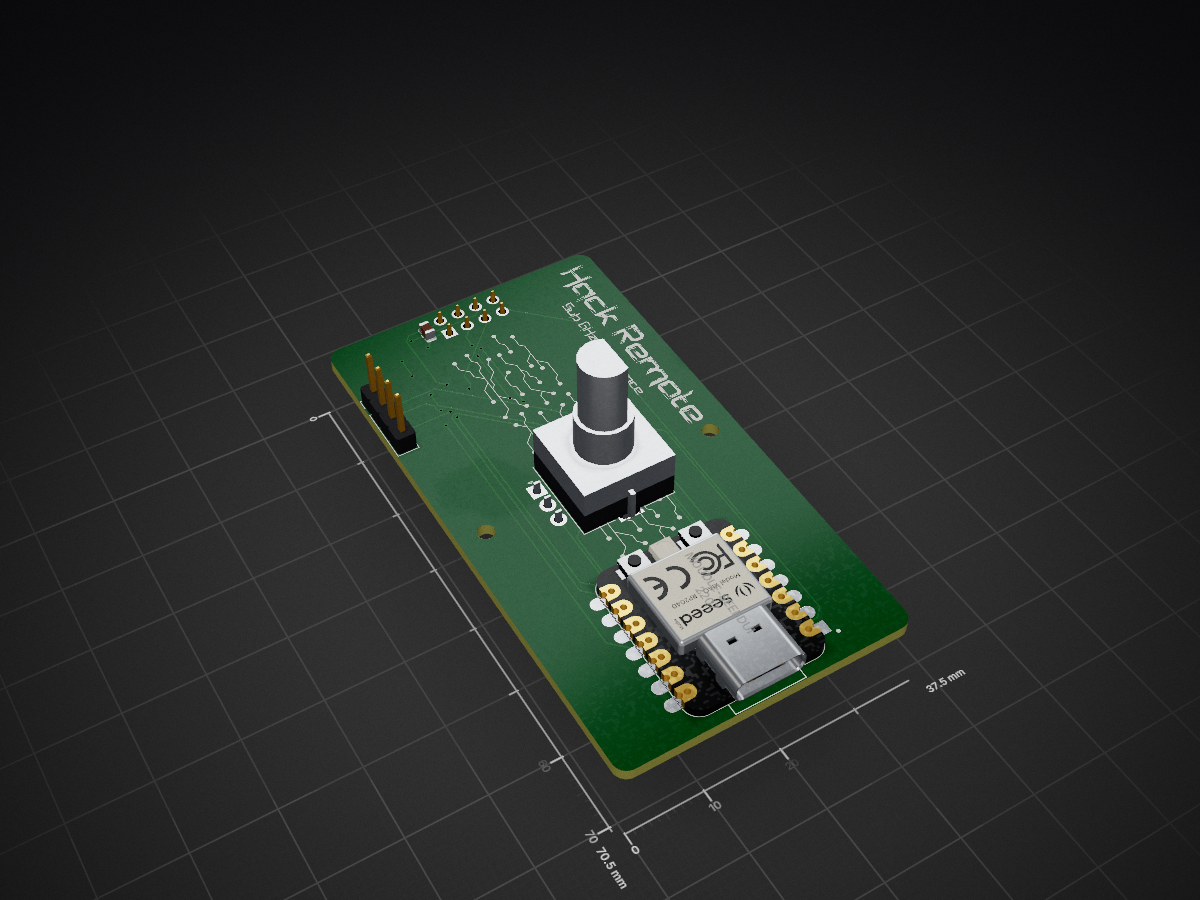
 Artgod13/Hack-Remote1
A cool remote that lets you control RF signals with a CC1101 module
Hack Remote is an open-source printed circuit board by Artgod13, from the Artgod13/Hack-Remote repository on GitHub. It is a 2-layer board of 37.5 × 70.5 mm with 7 parts on 15 nets, routed with 106 tracks and 19 vias.
Its parts include 2 ICs, 1 capacitor, 1 connector and 1 switch.
A cool remote that lets you control RF signals with a CC1101 module.
It has been specifically designed with customibilty in the code and ease of use in mind.
(Be careful to follow all radio laws in your area of jurisdiction)
How this works is when you plug it into a power source to turn it on, you open up to a menu of different Mhz frequencies. At this menu you can scroll through different Mhz frequencies and click the rotary encoder switch to send out you're desired signal. I also added a signal called 676767 (Really funny I know). When you choose this signal it sends out the same message on 50 randomly chosen Mhz frequencies on at a time in quick succession to "test" RF signal receivers. I have made the code simple and easy to understand so that someone can go in and add their own desired Mhz frequencies and messages.
I decided to make this, as I am constantly surrounded by RF receivers and transmitors. So why not build a simple device that is kinda like a flipper zero, and can manipulate/work with these RF signals. (Also flipper zeros are super expensive so if you want to make one but for like only RF here you go!)
Assembling the Hack Remote is very simple, all you need is a soldering iron, solder, 3d printed parts, PCB board, and all the parts in the BOM. First get the PCB board and place the compoments all facing up, and solder them onto their designated spots one by one. Next you want to flash the code onto the board, you do this by opening arduino IDE opening the code selecting the Xiao RP2040, and installing the Adafruit BusIO, AdafruitGFX Library, AdafruitSSD1306, RotaryEncoder, and SmartRC-CC1101-Driver-Lib Libraries. Then connnect you're board to the computer, and click upload on ArduinoIDE. After this get the Hack Remote bottom 3d printed part and put the assembled board onto it so that the Xiao usb-c end can be seen sticking out the power hole. Then screw the board on using 2 screws to make sure it stays in place. Finally put the Hack Remote Top on top of the bottom piece and use the rest of the screws to screw it in place. After all this work you should finally have a assembled Hack Remote ready to be used.
| Qty | Value | Footprint | References |
|---|---|---|---|
| 1 | 0.1uF | Capacitor_SMD:C_0805_2012Metric | C1 |
| 1 | Conn_01x04_Socket | Connector_PinHeader_2.54mm:PinHeader_1x04_P2.54mm_Vertical | J1 |
| 1 | MOUDLE-SEEEDUINO-XIAO | footprints:XIAO-Generic-Hybrid-14P-2.54-21X17.8MM | U1 |
| 1 | RotaryEncoder_Switch | Rotary_Encoder:RotaryEncoder_Alps_EC11E-Switch_Vertical_H20mm_MountingHoles | SW1 |
| 1 | ~ | Connector_PinSocket_2.54mm:PinSocket_2x04_P2.54mm_Vertical | U3 |
The 5 most common of 7 parts.
It measures 37.5 × 70.5 mm and has 2 copper layers, 1.6 mm thick.
7 parts. The full list of its parts is on this page, with links to each part's symbol and footprint where PCBKit's library has them.
From the Artgod13/Hack-Remote repository on GitHub, at the commit this page was made from: the board is PCB/HackRemote.kicad_pcb and its schematic PCB/Hack Remore.kicad_sch. PCBKit opens the board in the browser, with nothing to install.
Its repository states no licence, so its author keeps all rights: ask Artgod13 before reusing the design.
byrantech/laptop
anyon_e, a highly integrated, high end, open source laptop. Attempt the impossible.


AxxAxx/AxxSolder
STM32 Based soldering station for JBC cartridges, 9-24 VDC and USB-PD power


jamro/tiny-engineer
A small desktop robot that brings an AI coding assistant to life, physically acting out when it reads files, thinks, writes code, and finishes work.

hoglet67/RGBtoHDMI
Bare-metal Raspberry Pi project that provides pixel-perfect sampling of Retro Computer RGB/YUV video and conversion to HDMI
