


2 layers137 × 63 mm
Kickad
eljotx/SDR-TRX-on-ESP32-A1S
This repository describes an SDR transceiver based on the ESP32 A1S processor, using an ILI9341 color touchscreen display, and a Si5351 oscillator.
172 parts2

 arnavshah100/arnav-hackpad8
The arnav-hackpad is a mini-keyboard (or macropad) designed to act as an external number pad with navigation and mouse capabilities, too!
Arnav hackpad is an open-source printed circuit board by arnavshah100, from the arnavshah100/arnav-hackpad repository on GitHub, published under the MIT licence. It is a 2-layer board of 90.3 × 79.8 mm with 27 parts on 32 nets, routed with 250 tracks and 18 vias.
It is built around the PCF8574AT. Its parts include 12 switches, 10 diodes, 2 resistors, 2 ICs and 1 capacitor. It belongs with the keyboards and input boards of this library.
The arnav-hackpad is a mini-keyboard (or macropad) designed to act as an external number pad with navigation and mouse capabilities, too!
In my essential technology class at school, two of my favorite modules were coding and 3D printing. When I joined the Stardance summer program and started looking at the recommended projects, I saw hackpad, and saw it as a great way to combine my love for those two subjects.
This is my assembled macropad. Click on it to interact with the assembled macropad in Autodesk Fusion's web version.
Note: The assembled macropad CAD model is just a quick visual. Some of the dimensions have been edited to optimize its usability. The links of the individual parts below have the correct dimensions.
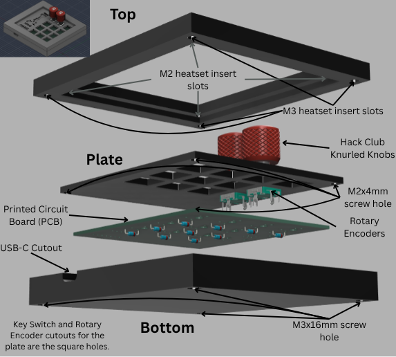
There are 3 parts to the case: the top, the bottom, and the plate. The arnav-hackpad is top-mounted, meaning that the plate is attached to the top part. The design gives an ≈0.3mm printing tolerance. Also, there are 2 knobs I have put on top of the rotary encoders, called Hack Club Knurled Knobs. To personalize it, I added a cool design with my name on the plate, which you can see in the plate demo below!
Click here to interact with the Plate.
Click here to interact with the Top part.
Click here to interact with the Bottom part.
Click here to interact with the Hack Club Knurled Knob.
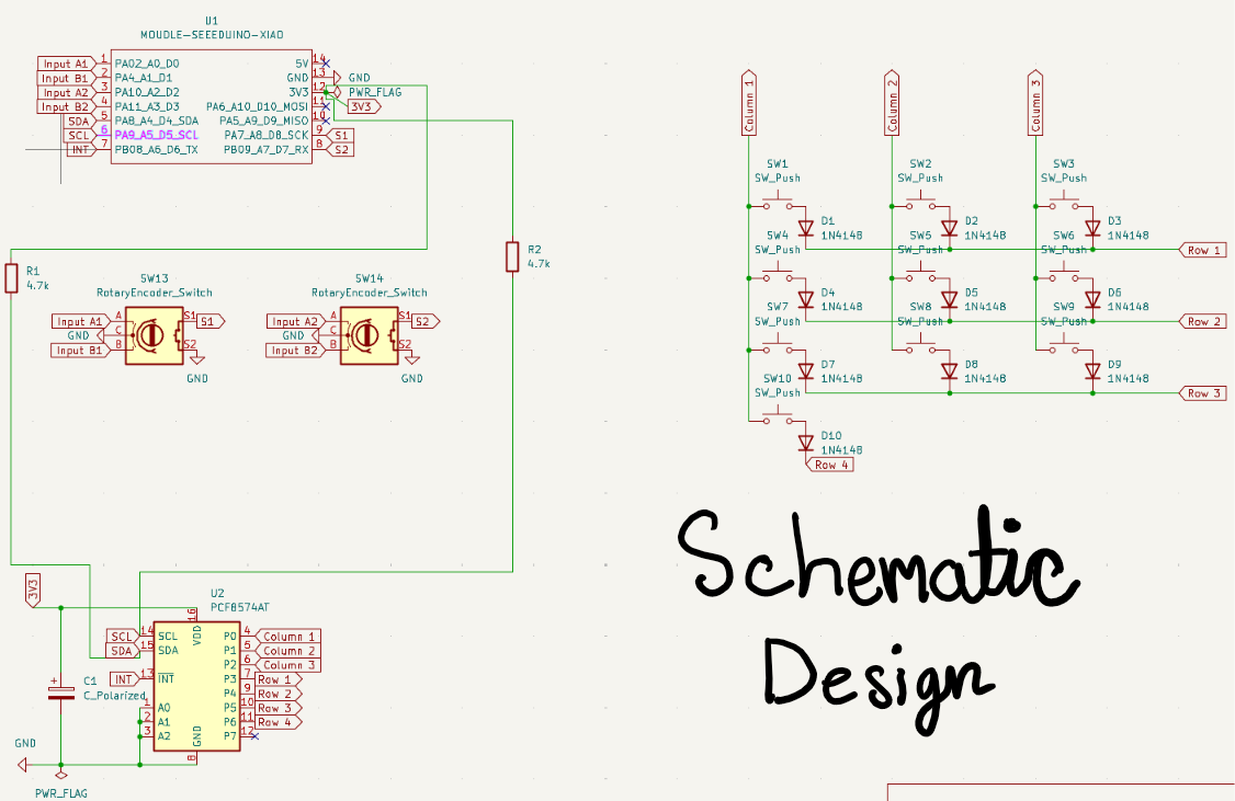
This is my PCB's schematic design. Click on it to interact with the schematic in KiCanvas.
I used a PCF8574AT I/O expander because all of the pins would not fit on the microchip.
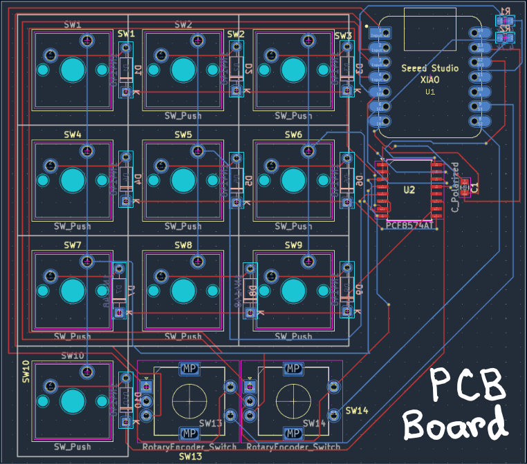
This is my PCB board. Click on it to interact with the PCB Board in KiCanvas.
I know it's very messy, but everything works out in the end!
The macropad is coded using KMK firmware. Layer 0 is made to take the place of a number pad, and Layer 1 is made to take the place of a mouse and the arrow keys. For the rotary encoders, clockwise is up, and counterclockwise is down.
Note: All of the key arrangements can be customized by simply editing the code.
If you need help for any part of this tutorial, Google can teach you!
To make this macropad, you will need the following:
Download the Production folder onto your computer. This guide, from Seeed Studio, is great to help you import the firmware. Drag the files out of the folder and into the drive. Make sure every file and folder is in the drive when you're done. The code can still be edited after you put it in the drive!
Use the Gerbers.zip file to print the PCB from whatever company you want. Make sure you choose the 2-layer PCB option. When you solder the components together, make sure to refer to the online PCB image often. I recommend soldering the components in this order:
Use the Plate.step file, Top.step file, Bottom.step file, and Hack Club Knurled Knob.step file in case you are using it. If you are printing it yourself, I suggest using google to figure out how to print on your specific 3D printer. Otherwise, just give the files above to whoever is printing it. Make sure you use either PLA, ABS, PETG, or Nylon, because certain plastics don't work with heatset inserts.
Finally, it's time to do the assembly! Put the M3 x D5mm x L4mm heatset inserts on the outer holes of the top part, and put the M2 x D4mm x L3mm heatset inserts on the inner holes of the top part. You can use this image to help you.
Next, carefully solder the keyswitches onto the PCB.
For the last step, use the M2x4mm screws to screw the plate onto the top part's M2 heatset insert. The top part of the screw should be touching the plate. I recommend plugging in the PCB into your device and trying using the macropad to check that it works. If your device doesn't register any of the keypresses, reread all the steps in the guide. Use the M3x16mm screws to screw the bottom part onto the top part's M3 heatset insert. The top part of the screw should be touching the bottom part. The labeled image showing where the screws should be is here.
Now, put the knobs on the rotary encoders, and you're DONE!
CELEBRATE!
After over 3 months of dedication, I have built the arnav-hackpad.
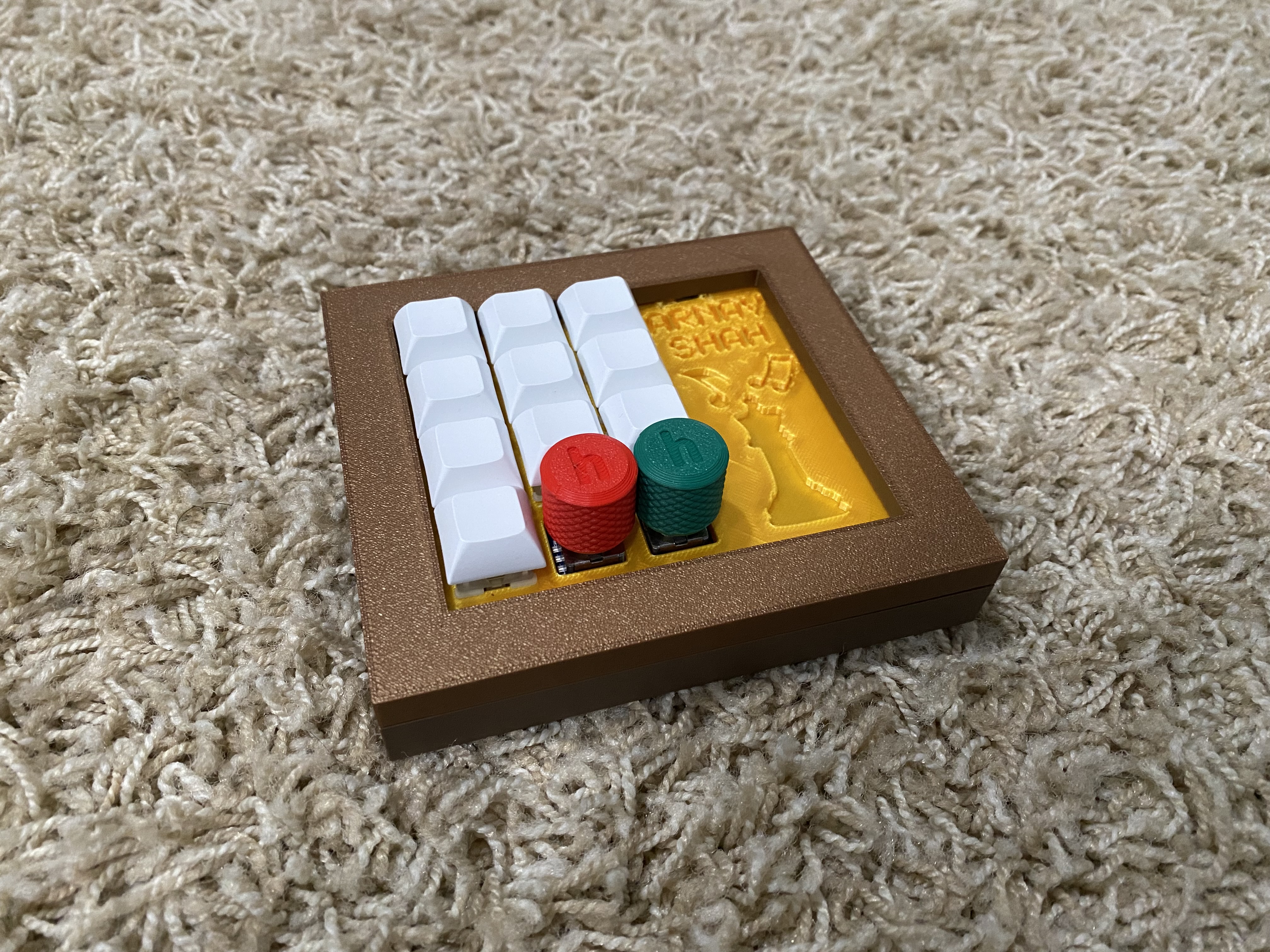 This is the image of the hackpad.
arnav-hackpad video
This is a video demoing the hackpad. Click on it to watch it!
The code is under an MIT License. For more info, see LICENSE.
Thank you for reading me!
| Qty | Value | Footprint | References |
|---|---|---|---|
| 10 | 1N4148 | Diode_THT:D_DO-35_SOD27_P7.62mm_Horizontal | D1, D2, D3, D4, D5, D6, D7, D8, D9, D10 |
| 10 | SW_Push | Button_Switch_Keyboard:SW_Cherry_MX_1.00u_PCB | SW1, SW2, SW3, SW4, SW5, SW6, SW7, SW8, SW9, SW10 |
| 2 | 4.7k | Resistor_SMD:R_0805_2012Metric | R1, R2 |
| 2 | RotaryEncoder_Switch | Rotary_Encoder:RotaryEncoder_Alps_EC11E-Switch_Vertical_H20mm | SW13, SW14 |
| 1 | C_Polarized | Capacitor_SMD:C_0805_2012Metric | C1 |
| 1 | MOUDLE-SEEEDUINO-XIAO | footprints:XIAO-Generic-Hybrid-14P-2.54-21X17.8MM | U1 |
| 1 | PCF8574AT | Package_SO:SOIC-16W_7.5x10.3mm_P1.27mm | U2 |
It measures 90.3 × 79.8 mm and has 2 copper layers, 1.6 mm thick.
27 parts, built around the PCF8574AT. The full list of its parts is on this page, with links to each part's symbol and footprint where PCBKit's library has them.
From the arnavshah100/arnav-hackpad repository on GitHub, at the commit this page was made from: the board is PCB/KiCad file.kicad_pcb and its schematic PCB/KiCad file.kicad_sch. PCBKit opens the board in the browser, with nothing to install.
Its repository publishes it under the MIT licence: you may reuse it on that licence's terms (keep the author's notice, and for a copyleft licence share your changes alike).
eljotx/SDR-TRX-on-ESP32-A1S
This repository describes an SDR transceiver based on the ESP32 A1S processor, using an ILI9341 color touchscreen display, and a Si5351 oscillator.

peterus/OpenDriveHub
Open-source modular control platform for functional model vehicles, featuring bidirectional communication, telemetry, and plug-in hardware modules.

Shuri-101/MacroPad
Macro Pad for use in CAD and general productivity + convenience, mainly for use in CAD...

CedricL1u/Chronos
Chronos is a fully mechanical 7‑segment Pomodoro timer and clock that uses cams, servos, and a custom ESP32‑C3 PCB to create a kinetic, alarm‑equipped display that makes focus sessions more engaging.

Hirusha785/esp8266-16-channel-relay-module
⚡ ESP8266-based 16-channel Wi-Fi relay controller designed in KiCad for IoT, automation, and remote switching applications.

koko69420/Solar-Panel-Wash-Controller
Automated scheduled solar panel washing controller PCB with RTC timing and pump relay actuation in KiCad

oct-karim/Mini-Power-Gauge
A mini power gauge that mesures current and voltage.
