4 layers117.9 × 99.1 mm
GNSS Firehose
pmonta/GNSS_Firehose
Wideband front-end digitizer for GPS, GLONASS, Galileo, BeiDou
519 parts69

 CedricL1u/Chronos
Chronos is a fully mechanical 7‑segment Pomodoro timer and clock that uses cams, servos, and a custom ESP32‑C3 PCB to create a kinetic, alarm‑equipped display that makes focus sessions more engaging.
Mechanical Pomodoro Timer is an open-source printed circuit board by CedricL1u, from the CedricL1u/Chronos repository on GitHub, published under the MIT licence. It is a 2-layer board of 82 × 47.5 mm with 41 parts on 43 nets, routed with 307 tracks and 43 vias.
It is built around the PCF8574AT, AOD403 and PJ-063BH, with the SM5819 among its other parts. Its parts include 12 resistors, 7 capacitors, 6 connectors, 4 ICs and 1 diode. It belongs with the lEDs and displays boards and the ESP32 and RISC-V boards of this library.


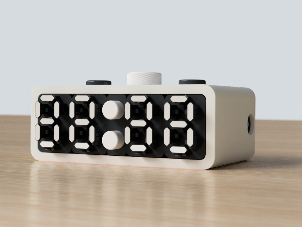
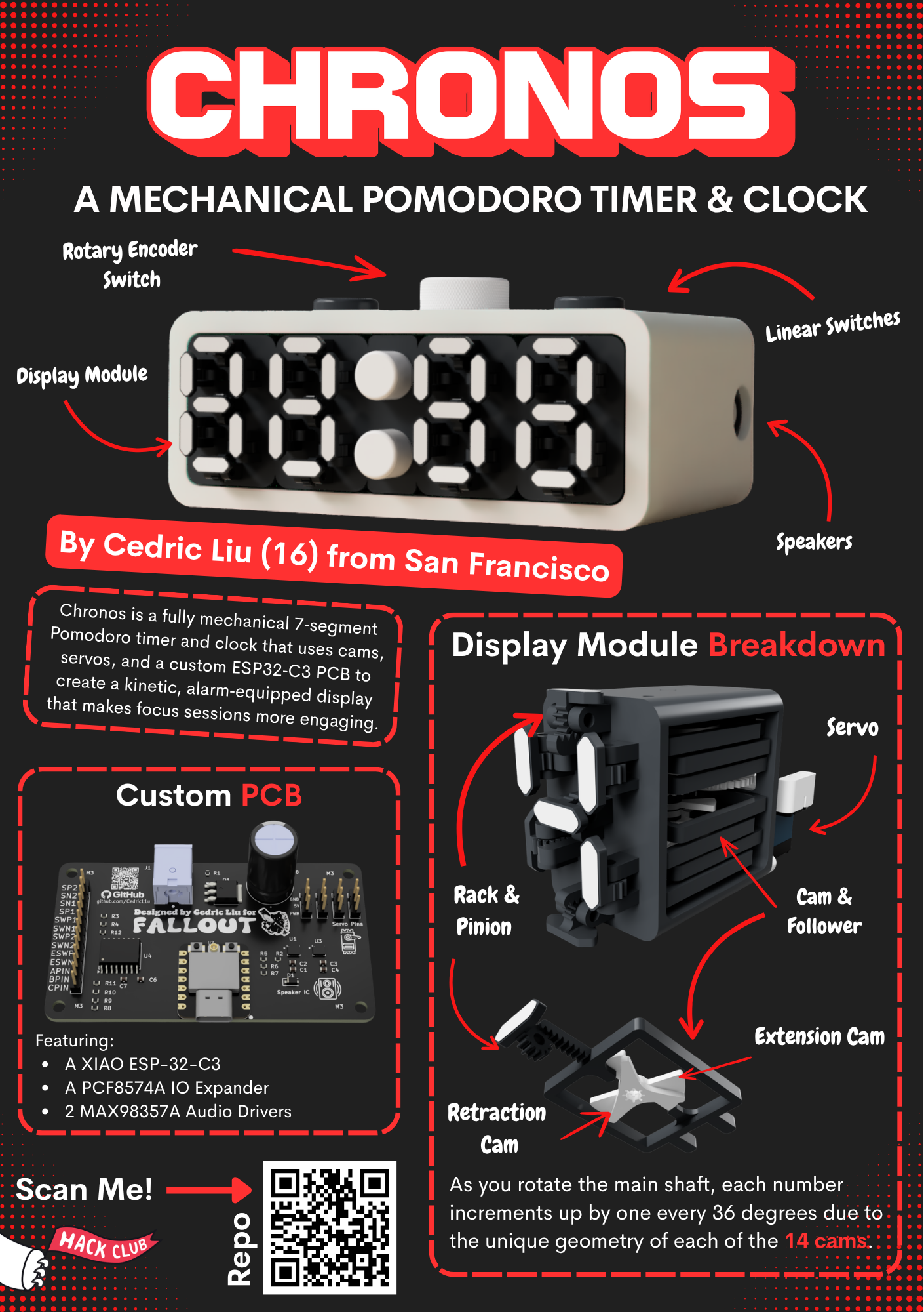
Chronos is a 7-Segment mechanical display that is supposed to function as a pomodoro timer, clock, or as a regular timer. It’s equipped with speakers that play an alarm noise when time is up and also random sound effects throughout the timer. The speakers let the user know how many pomodoro cycles they have completed after each cycle. They also help Chronos function as an alarm clock when it is put into clock mode. On the top there are two buttons and a rotary encoder which serve as inputs to control it. Chronos is powered by a ESP32-C3 on a custom PCB that drives all the electronics. This device is named Chronos because in Greek it means the quantitative measurement of time that ticks away on a clock.
Chronos was mainly built to function as a pomodoro timer, but since it has four numerical displays I decided to make it usable as a clock and regular timer as well. In case you don’t know what a Pomodoro timer is, it’s a simple timer that is used with the Pomodoro Technique. The Pomodoro Technique is a study strategy where you work in short focused intervals (usually 25 minutes) followed by brief breaks (about 5 minutes). You repeat this cycle four times and then you take a longer 15-30 minute break. It’s meant to help you stay focused, reduce procrastination, and make long tasks feel more manageable by splitting them into these repeating cycles. As a student myself who struggled with procrastination and locking in during study sessions I found the pomodoro technique to be extremely useful. I mainly used online timers I found but I found them to be kind of boring so I came up with this device. It’s extremely satisfying because it makes a click every time a digit changes and it’s also cool to see as I study. It’s kind of like an ASMR sound effect while I work or study.
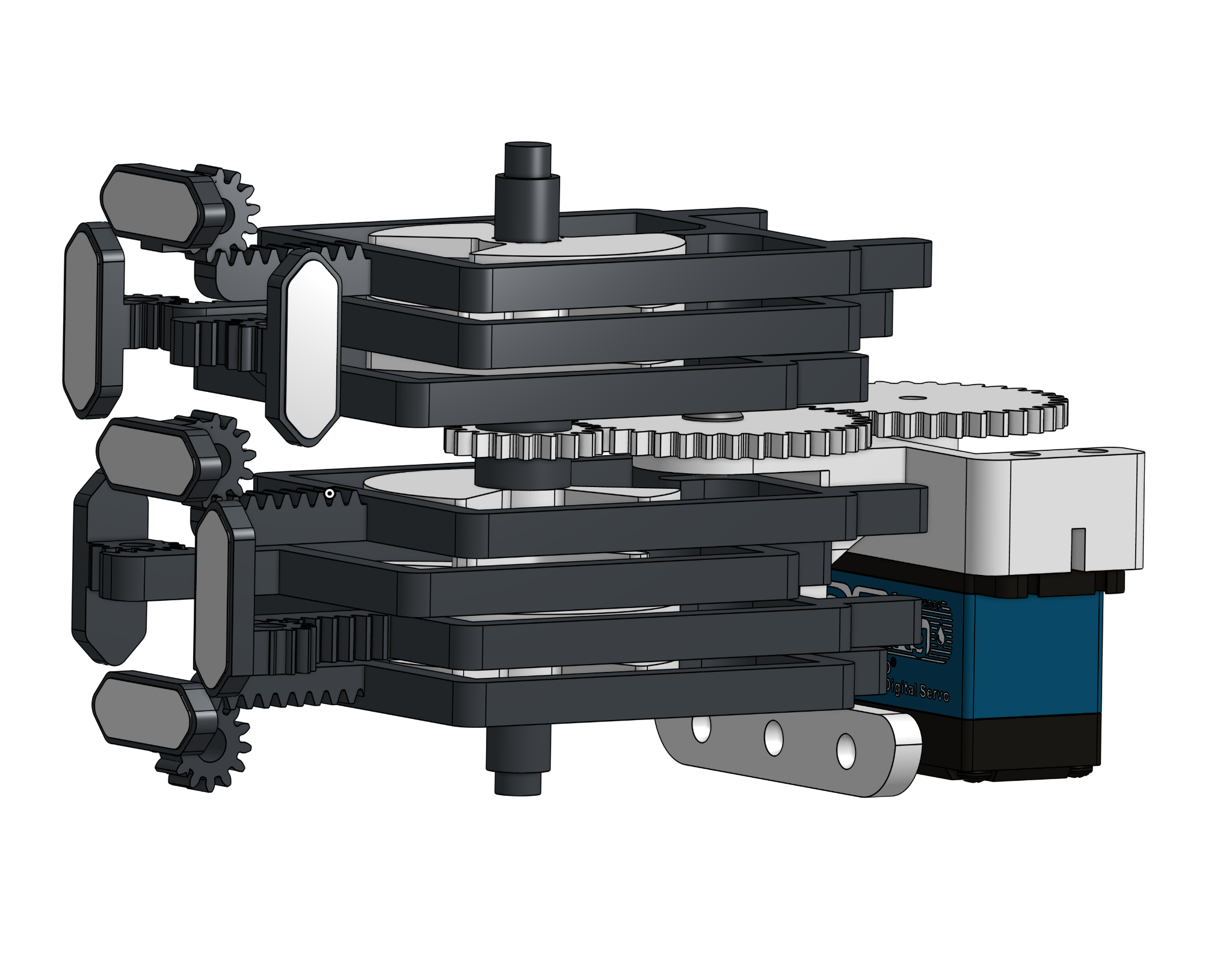
The clock works through four display modules each with seven segments. Each of these 7 segments are connected to a rack and pinion which drives each segment and controls when each segment is displayed and not displayed.
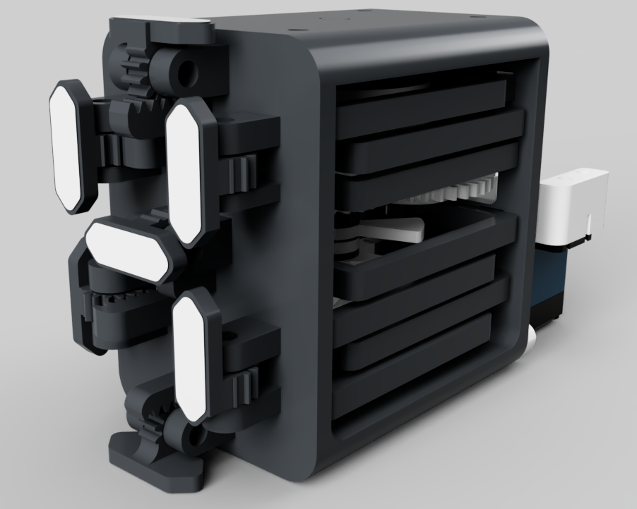
Each of these racks are driven by a cam and follower mechanism that pushes each rack individually. There is a stack of 14 cams and each follower has 2 cams. One to retract it and one to extend it. Depending on the angle of the shaft different cams are extended and different cams are retracted which control the number displayed. Numbers are displayed at a 36 degree increment of the shaft. For example at 0 degrees the number 0 is displayed and at 72 degrees the number 2 is displayed.
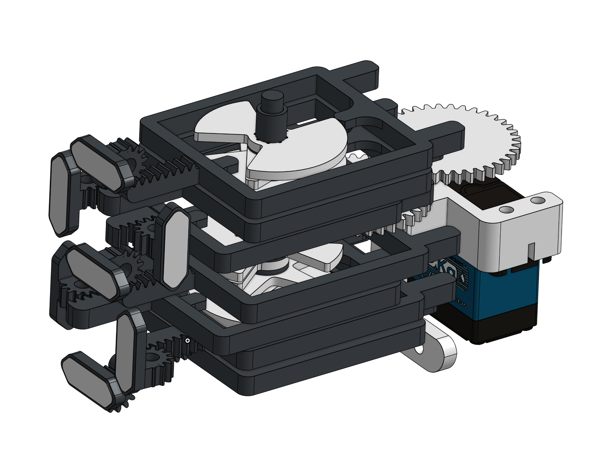
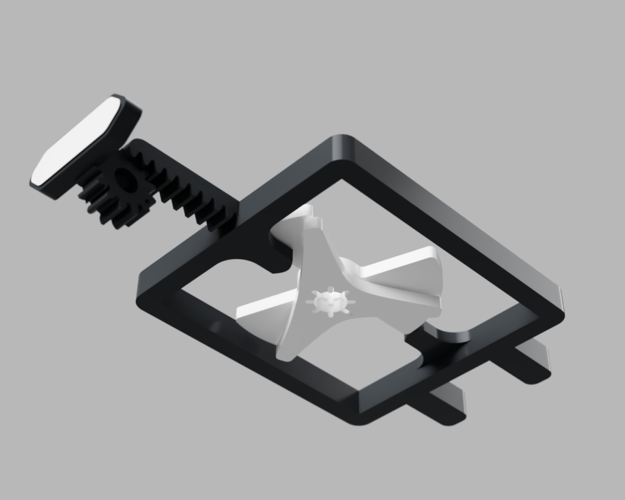
The shaft is driven by a servo that is geared to it.
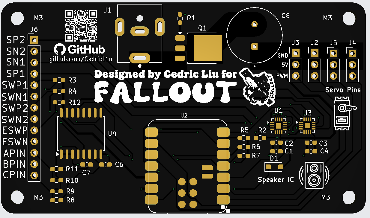
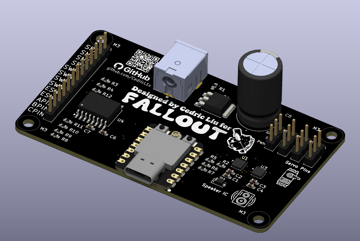
This device is powered by a custom PCB I made in KiCAD that utilizes a Seed Studio XIAO ESP32-C3. On my board I have 4 servo pins which are driven by PWM signals from my microcontroller and the 5V power. There are also two MAX98357A Audio Drive ICs used to control the speakers on my device. I also have a 8-bit IO Expander IC because there weren’t enough GPIO pins on my microcontroller. The 8-Bit IO Expander communicates with my microcontroller through I2C and controls my rotary encoder switch and my two linear switches. The PCB is powered by a 8A 5V AC-DC unit that I plug into the wall and connect into my barrel jack connector. From there the power goes into a reverse polarity mosfet circuit that blocks current if the power supply is connected backwards. This P channel mosfet is then connected to my bulk 2200uF bulk capacitor that acts like a power reservoir to prevent brownouts in case the servos suddenly stall.
There are 3 methods of input into the clock. A rotary encoder switch, and two cherry mx style linear mechanical keyboard switches. When you rotate the white knob in the middle you can change the duration of the timer when you are in the pomodoro or timer mode. When you click it you can pause or resume the clock. The right button lets you switch between clock mode, pomodoro mode, and timer mode. The left button lets you skip between pomodoro cycles.
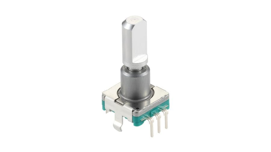 EC11EA5 Rotary Encoder Switch
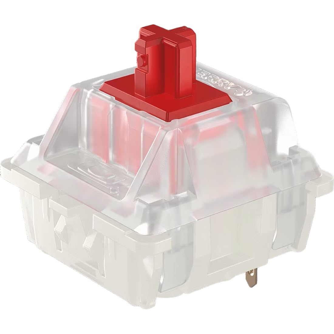 Cherry MX Style Linear Mechanical Keyboard Switch
After you've printed all you're parts you want to first start by putting all of your fikkiwers into the front part of the casing. After you've done that you should align all of your cams on your shaft and place them all into their with your spacers. Once you've done that you need to put the cams into the followers. This can be a bit tricky, a tip I found useful was to wiggle the cams and move the followers when the cams get stuck. This can take a while but after you've done that you need to put the top plate on and screw it in, this will lock the shaft in place. After that mount the servo holder onto the back case plate and screw the servo onto the servo holder. Then screw in the servo gear and attach the back case plate into the rest of the case and align the followers such that they fit inside the hole. Repeat this 3 more times and you should have all 4 display modules. Once you have your display modules, you should first wire everything up. Wire all the jumper cables and servo wires from the pcb to their respective components. Then screw in the PCB and mount all 4 display modules, the 2 speakers, and then screw in the back plate for the case and you should be all good to go.
| Qty | Value | Footprint | References |
|---|---|---|---|
| 11 | 10k | Resistor_SMD:R_0603_1608Metric_Pad0.98x0.95mm_HandSolder | R1, R3, R4, R5, R6, R7, R8, R9, R10, R11, R12 |
| 6 | LOGO | LOGO | G***, G***, G***, G***, G***, Speakers |
| 4 | MountingHole_3.2mm_M3 | MountingHole:MountingHole_3.2mm_M3 | M3, M3, M3, M3 |
| 4 | Servo Connector Pin | Connector_PinHeader_2.54mm:PinHeader_1x03_P2.54mm_Vertical | J2, J3, J4, J5 |
| 2 | 0.01uF | Capacitor_SMD:C_0603_1608Metric_Pad1.08x0.95mm_HandSolder | C6, C7 |
| 2 | 0.1uF | Capacitor_SMD:C_0603_1608Metric_Pad1.08x0.95mm_HandSolder | C2, C4 |
| 2 | 10uF | Capacitor_SMD:C_0603_1608Metric_Pad1.08x0.95mm_HandSolder | C1, C3 |
| 2 | MAX98357A | Package_DFN_QFN:TQFN-16-1EP_3x3mm_P0.5mm_EP1.23x1.23mm | U1, U3 |
| 1 | 13 Pin Headers | Connector_PinHeader_2.54mm:PinHeader_1x13_P2.54mm_Vertical | J6 |
| 1 | 210k | Resistor_SMD:R_0603_1608Metric_Pad0.98x0.95mm_HandSolder | R2 |
| 1 | 2200uF | Clockparts:CAPPRD500W60D1250H2000 | C8 |
| 1 | AOD403 | Package_TO_SOT_SMD:TO-252-3_TabPin2 | Q1 |
| 1 | PCF8574AT | Package_SO:SOIC-16W_7.5x10.3mm_P1.27mm | U4 |
| 1 | PJ-063BH | Clockparts:CUI_PJ-063BH | J1 |
| 1 | SM5819 | Diode_SMD:D_SOD-123F | D1 |
| 1 | XIAO-ESP32-C3-DIP | Clockparts:XIAO-ESP32-C3-SMD | U2 |
It measures 82 × 47.5 mm and has 2 copper layers, 1.6 mm thick.
41 parts, built around the PCF8574AT, AOD403, PJ-063BH and SM5819. The full list of its parts is on this page, with links to each part's symbol and footprint where PCBKit's library has them.
From the CedricL1u/Chronos repository on GitHub, at the commit this page was made from: the board is Electronics/Mechanical Pomodoro Timer.kicad_pcb and its schematic Electronics/Mechanical Pomodoro Timer.kicad_sch. PCBKit opens the board in the browser, with nothing to install.
Its repository publishes it under the MIT licence: you may reuse it on that licence's terms (keep the author's notice, and for a copyleft licence share your changes alike).
pmonta/GNSS_Firehose
Wideband front-end digitizer for GPS, GLONASS, Galileo, BeiDou

precision-sustainable-ag/PlantMap3D-Hardware
The system management board handles all power distribution in the multi-camera system and a few other auxiliary functions. The PCB is designed using KiCad.

pa3gsb/Radioberry-2.x-extensions
Hardware extensions to the Radioberry Ham Radio


LostInCompilation/WLED-Controller-PCB
WLED Controller Board with ESP32 - 4 Channels - Current and Power Monitoring - INMP441 Microphone


doug7410/nowplaying-appliance
Build guide, BOM and hardware for the Now-Playing desk appliance: HUB75 spectrum + touch now-playing display driven by room-mic song recognition
